Direct-injection type concave cavity swirl nozzle

A swirl nozzle and concave cavity technology, applied in the field of direct-shot concave cavity swirl nozzles, can solve the problems of total pressure loss, nozzle blockage, affecting the stability and reliability of the engine combustion chamber, etc., to improve fuel atomization quality, The effect of reducing fuel distribution and shortening fuel atomization distance

Active Publication Date: 2020-08-11
NORTHWESTERN POLYTECHNICAL UNIV
View PDF15 Cites 0 Cited by
  • Summary
  • Abstract
  • Description
  • Claims
  • Application Information

AI Technical Summary

Problems solved by technology

The high-speed airflow from the compressor is mixed with the fuel through the swirler to provide the combustion chamber with a suitable fuel-air ratio for combustion, and a stable flame is generated in the recirculation area near the outlet of the head; and the direct-firing fuel nozzles commonly used at present, due to etc. The effective diameter is small, which can easily lead to the problem of nozzle clogging, which will cause obvious total pressure loss and affect the stability and reliability of the engine combustion chamber. Therefore, the research on fuel injection mode and fuel atomization effect has always Important Aspects of Ministry Studies

Method used


Image

  • Direct-injection type concave cavity swirl nozzle
  • Direct-injection type concave cavity swirl nozzle
  • Direct-injection type concave cavity swirl nozzle

Examples


Embodiment Construction

[0020] The present invention will be further described now in conjunction with accompanying drawing:

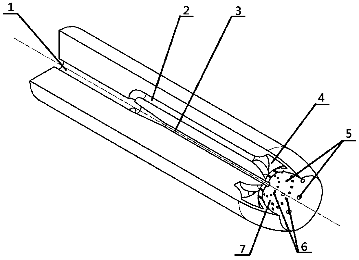
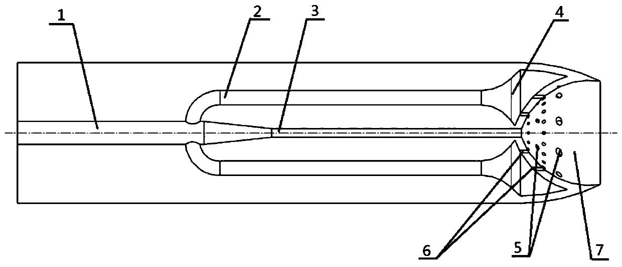
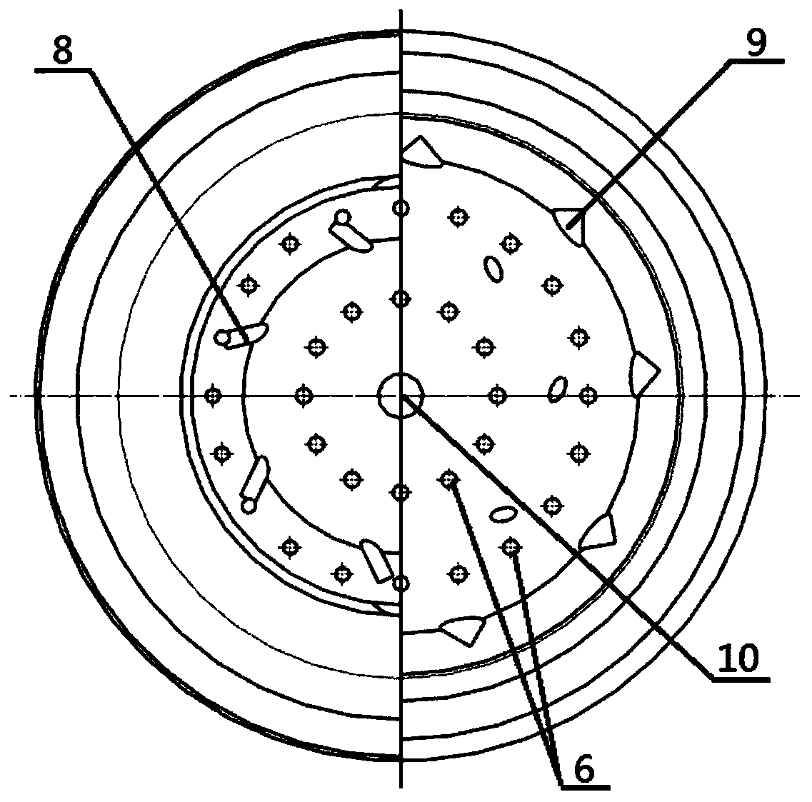
[0021] combine figure 1 , figure 2 , image 3 , the invention provides a technical proposal of a direct-injected concave cavity swirl nozzle. figure 1 It is a schematic diagram of the overall structure of the straight-shot concave cavity swirl nozzle, figure 2 It is a cross-sectional view of the central axis of the direct-injected concave swirl nozzle, image 3 It is a cross-sectional view of the radial oil injection hole on the head of the direct-injection concave swirl nozzle.

[0022] Specific process: the fuel enters the nozzle through the oil inlet hole (1), and is divided into a side oil delivery pipe (2) and a central oil delivery pipe (3) at 1 / 3 of the total length. ) is sprayed out, and the side fuel pipe (2) sends fuel into the annular cavity (4) to supply fuel to the multi-stage fuel injection holes, and the fuel sprayed from the radial fuel injection holes ...


PUM

PropertyMeasurementUnit
Diameteraaaaaaaaaa
Diameteraaaaaaaaaa

Abstract

The invention provides a direct-injection type concave cavity swirl nozzle. The direct-injection type concave cavity swirl nozzle comprises an oil inlet hole, oil conveying pipes, a ring cavity, a concave cavity, oil injection holes and other structures. The direct-injection type concave cavity swirl nozzle has the main advantages that compared with a conventional direct-injection type nozzle, thehead is provided with the concave cavity structure, fuel oil of an inner center oil conveying pipe is directly injected out from a center oil injection hole, fuel oil is conveyed by two side oil conveying pipes to enter the ring cavity and then is injected out by the four rows of staggered oil injection holes (the direct-injection oil injection holes and the radial oil injection holes), narrow-range weak swirling flow can be formed in the concave cavity, fuel oil crushing can be accelerated, the fuel oil atomization distance can be shortened, the fuel oil atomization quality can be improved,and pollutant discharge can be effectively reduced by uniform fuel oil distribution.

Description

technical field [0001] The invention relates to the field of aero-engine combustors, in particular to a direct-injected concave cavity swirl nozzle. Background technique [0002] With the continuous development of the aviation industry, higher requirements are put forward for the performance of aero-engines. Modern aero-engines are developing in the direction of high performance, high thrust-to-weight ratio, low emissions and economy. In order to meet the current requirements for engines, the engine design All aspects are facing enormous challenges. Among them, the combustion chamber is the main power supply structure of the aero-engine, its main function is to diffuse the pressure and reduce the speed, prepare fuel, form a low-speed zone or a recirculation zone to stabilize the flame, and the performance of the combustion chamber directly affects various indicators such as engine thrust and emissions. Therefore, the design of the combustion chamber is particularly importan...

Claims


Application Information

Patent Timeline
IPC IPC(8): F23R3/38
CPCF23R3/38
Inventor 张群曹婷婷胡凡李小龙程祥旺
Owner NORTHWESTERN POLYTECHNICAL UNIV
Why Eureka
Try Eureka