Battery residual life prediction method considering recovery effect based on uncertain process

A technology for determining the process and life prediction, applied in the direction of prediction, measuring electricity, measuring devices, etc., can solve the problems of battery available capacity increase, parameter cognition uncertainty, similarity degree cognition uncertainty, etc.

Active Publication Date: 2020-08-11
BEIHANG UNIV
View PDF3 Cites 5 Cited by
  • Summary
  • Abstract
  • Description
  • Claims
  • Application Information

AI Technical Summary

Problems solved by technology

First, the current methods based on statistical models are all based on probability theory. In probability theory and data statistics, according to the theorem of large numbers, when the detection samples are sufficient, the frequency approaches probability. In the degradation of actual equipment, The data that can be monitored is often limited, so the cognitive uncertainty of the parameters will be introduced; second, for some practical application scenarios, the recovery phenomenon in the degradation process must be considered, but this phenomenon is in the existing In the degradation model, it is often ignored. A common example of the recovery phenomenon in the degradation process is the degradation of the battery, including the degradation of the lithium-ion battery and the degradation of the proton exchange membrane fuel cell. In the lithium-ion battery, when the battery is charging Pausing for a period of time during the discharge cycle, the chemical reaction inside the battery will increase the available capacity of the battery in the next cycle, and there are many cognitive uncertainties about the occurrence of this recovery phenomenon; third, in the remaining life prediction, due to Models are built based on historical information about similar parts, so there is cognitive uncertainty about the degree of similarity between individual parts and population parts

Method used


Image

  • Battery residual life prediction method considering recovery effect based on uncertain process
  • Battery residual life prediction method considering recovery effect based on uncertain process
  • Battery residual life prediction method considering recovery effect based on uncertain process

Examples


Embodiment Construction

[0067] The application will be further described in detail below in conjunction with the accompanying drawings and embodiments. It should be understood that the specific embodiments described here are only used to explain related inventions, rather than to limit the invention. It should also be noted that, for the convenience of description, only the parts related to the related invention are shown in the drawings.

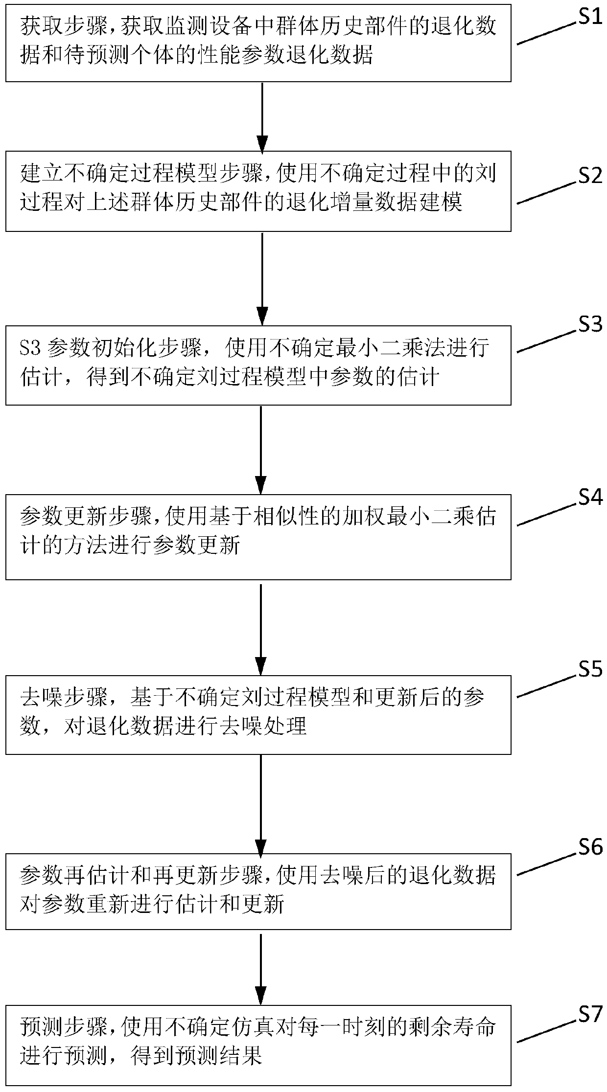
[0068] The method of the present invention can be used for memory modeling and calculation of the degradation process with recovery phenomenon, and the output is the prediction result of the remaining life of the component with the degradation process, which can be applied to fields such as fault assessment and maintenance decision-making.

[0069] It should be noted that, in the case of no conflict, the embodiments in the present application and the features in the embodiments can be combined with each other. The present application will be described in detail b...


PUM


Abstract

The invention provides a battery remaining life prediction method considering a recovery effect based on an uncertain process, and the method comprises the following steps: S1, an obtaining step: obtaining degradation data; S2, a step of establishing an uncertain process model, namely modeling degradation increment data by using a Liu process in an uncertain process; S3, a parameter initializationstep: performing estimation by using an uncertain least square method to obtain a parameter estimation value; S4, a parameter updating step: performing parameter updating by using a weighted least square estimation method; S5, a denoising step: based on the uncertain Liu process model and the updated parameters, denoising the degradation data; S6, a parameter re-estimation and re-updating step: re-estimating and re-updating the parameters by using the denoised degradation data; and S7, a prediction step: using uncertain simulation to obtain a prediction result of the residual life. Accordingto the method, the cognitive uncertainty of the residual life prediction model is improved, the recovery phenomenon in degradation is considered, and the degradation prediction accuracy is improved.

Description

technical field [0001] The invention relates to the technical field of component remaining life prediction, in particular to a battery remaining life prediction method based on an uncertain process and considering recovery effects. Background technique [0002] Remaining life prediction refers to the length of the time period between the current operating time and failure time of individual components. Remaining life prediction plays an important role in condition-based maintenance, and condition-based maintenance is an effective maintenance strategy. The method is based on historical information of similar components and real-time information of components to be predicted. Condition-based maintenance has been widely used in the fields of ships, aviation and transportation. This maintenance strategy has attracted widespread attention in recent years because it can reduce unnecessary maintenance costs while ensuring product safety and reliability. It is worth noting that th...

Claims


Application Information

Patent Timeline
Patent Type & Authority Applications(China)
IPC IPC(8): G06Q10/04G06F30/20G01R31/392G01R31/367G06F119/04
CPCG06Q10/04G06F30/20G01R31/392G01R31/367G06F2119/04
Inventor 张森榉康锐林焱辉
Owner BEIHANG UNIV
Why Eureka
Try Eureka