A device and method for flue gas denitrification using a microbial fuel cell combined with a microbial electrolytic cell

A technology of microbial electrolysis cell and fuel cell, which is applied in the field of engineering, can solve the problems of conductor temperature rise, increase safety measures, and large current, and achieve the effects of improving tolerance, reducing fire, and reducing waste of electric energy

Active Publication Date: 2021-08-06
SOUTH CHINA UNIV OF TECH
View PDF4 Cites 0 Cited by
  • Summary
  • Abstract
  • Description
  • Claims
  • Application Information

AI Technical Summary

Problems solved by technology

However, in the existing technology, CABER flue gas denitrification consumes energy and costs high; MFC flue gas denitrification only achieves the activation of circulating fluid, but does not involve the direct reduction of flue gas MFC; MEC flue gas denitrification has the disadvantage of energy consumption , the cost is high, and the direct use of the power supply has disadvantages such as large current, easy to increase the temperature of the conductor, and additional safety measures.

Method used


Image

  • A device and method for flue gas denitrification using a microbial fuel cell combined with a microbial electrolytic cell
  • A device and method for flue gas denitrification using a microbial fuel cell combined with a microbial electrolytic cell

Examples


Embodiment 1

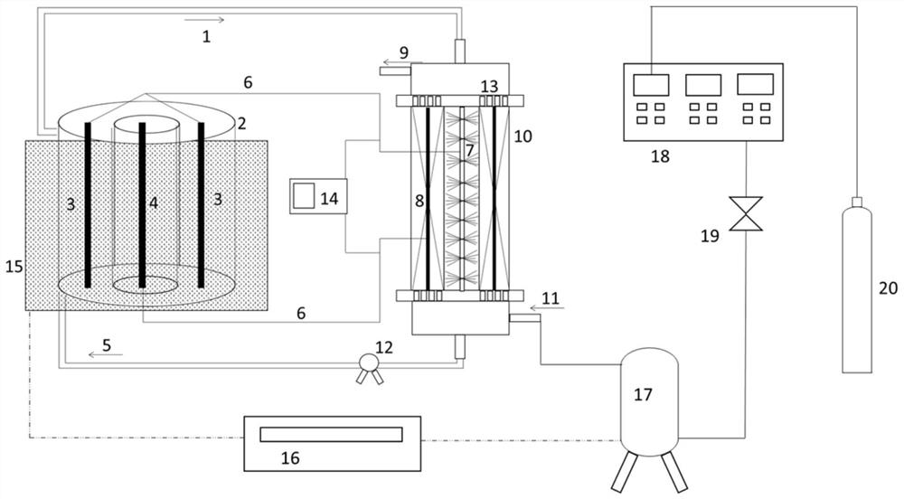
[0039] MFC-MEC flue gas denitration device, such as figure 1 As shown, the MFC and MEC have the same structure size, and they are both sleeve-type structures. The anode is inside and the cathode is on the outer ring. The inner diameter of the anode inside the MFC is 5.4cm, and the height is 20cm. The inner diameter of the MFC cathode is 10cm, and the height is 20cm. An exchange membrane (PEM, Nafion 117, Dupont, USA) was wrapped on a perforated cylinder with an outer diameter of 6 cm and a height of 20 cm. As shown in the figure, there is an empty chamber on the upper and lower sides of the MFC, the height of the empty chamber is 7cm, and the inner diameter is 10cm. The anode and cathode are placed in each of the two devices. The diameter of the MFC anode carbon brush is 5cm, the cathode graphite rod and graphite particles are 6mm, the graphite particle length is 10cm, and the graphite felt filler is 1*1*2cm.

[0040] The cathode 8 of the MFC is connected to the MEC anode 4 t...

Embodiment 2

[0050] The difference between this embodiment and embodiment 1 is:

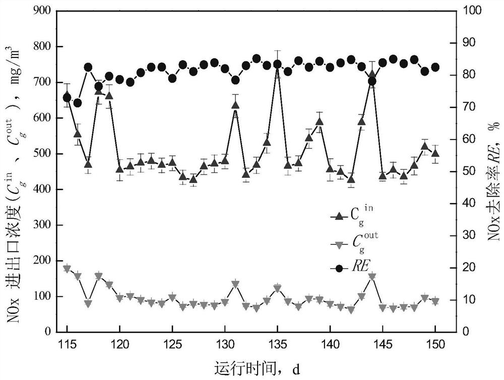
[0051] (1) Artificially synthesized waste gas: NOx 450-750mg / m3, the flue gas is fed for 8 hours a day, and the flue gas flow rate is 60m3 / h.

[0052] (2) Inoculate the cultured strains on the filler, measure the NOx removal efficiency regularly, start the cycle film formation for about 115 days, and measure the waste gas removal efficiency up to 80%, and the film formation is successful. The device runs for 150 days, and the denitrification efficiency can be maintained at 85% in the end.

Embodiment 3

[0054] Exhaust gas from a coal-fired boiler, flue gas flow rate 45000m 3 / h, NO content is 500mg / m 3 , according to the process of the present invention as follows:

[0055] (1) According to the composition of the exhaust gas, the denitrification tower is a cylindrical sleeve type microbial fuel cell. The diameter of the microbial fuel cell tower is 9m and the height is 20m. The bristle diameter of the brush is 4m. The diameter of the inner wall of the external reactor is 9m. The cathode is filled with graphite rods and carbon felt. The particle size of the filler is 2 cm and the length is 3 cm. 12 graphite rods are inserted into the filler, arranged equidistantly and circled around the anode. The diameter of the graphite rod is 2 cm. , 10m long. In this embodiment, the anode carbon source is the sewage from the secondary sedimentation tank of the slaughter wastewater sewage plant, the cathode uses glucose solution 5g / L, and Fe(II)EDTA is used as the absorbent in the absorp...


PUM

PropertyMeasurementUnit
diameteraaaaaaaaaa
diameteraaaaaaaaaa
particle diameteraaaaaaaaaa

Abstract

The invention discloses a device and method for flue gas denitrification using a microbial fuel cell combined with a microbial electrolytic cell. The cathode of the MFC is connected to the anode of the MEC through a wire, the anode of the MFC is connected to the cathode of the MEC through a wire, and the anode chamber of the MFC and the MEC and The cathode chambers are separated by a proton exchange membrane; the bottom of the MFC cathode is provided with a flue gas inlet and a nutrient solution outlet, and the top of the MFC cathode is provided with a flue gas outlet and a nutrient solution inlet. The cathode chamber of the MFC and the cathode chamber of the MEC are There is a nutrient solution circulation loop between them; the electrons generated by the MFC are used as a power source to act on the MEC, and under the double strengthening of the MEC and the MFC, the flue gas denitrification is realized. The invention has low cost and low energy consumption, and the NOx in the flue gas is transferred to the liquid phase through the chemical absorbent, and the pollutants are removed and the absorbent is activated through the MFC-MEC joint technology, so that the high-efficiency and greenness of the medium-temperature flue gas can be realized Denitrification.

Description

technical field [0001] The invention belongs to the field of engineering technology, and in particular relates to a device and method for removing nitrogen oxides at medium temperature by using a microbial fuel cell combined with a microbial electrolytic cell. Background technique [0002] According to the statistics of the Ministry of Environmental Protection, my country's flue gas emissions have increased year by year, and the total emissions have only increased. At present, the traditional flue gas treatment technologies include selective catalytic reduction, selective non-catalytic reduction, biological method and chemical absorption method. Among all technologies, flue gas biological denitrification has broad application prospects, among which the new technology of bioelectrochemical flue gas denitrification has promoted the development direction of flue gas denitrification. Bioelectrochemical systems include microbial fuel cells (MFCs) and microbial electrolysis cells...

Claims


Application Information

Patent Timeline
Patent Type & Authority Patents(China)
IPC IPC(8): B01D53/84B01D53/56B01D53/32H01M8/16C02F3/34C02F3/00
CPCB01D53/32B01D53/56B01D53/84B01D2258/0283B01D2259/812C02F3/005C02F3/34H01M8/16Y02E60/50Y02A50/20
Inventor 黄少斌黄行柱
Owner SOUTH CHINA UNIV OF TECH
Why Eureka
Try Eureka