
Deceleration strip for sponge city

A sponge city and speed bump technology, applied in drinking water installations, general water supply conservation, roads, etc., can solve problems such as easy obstruction of rainwater flow, unfavorable rainwater discharge, and single function of speed bumps.

Active Publication Date: 2020-08-14
赵伯阳
View PDF5 Cites 1 Cited by
  • Summary
  • Abstract
  • Description
  • Claims
  • Application Information

AI Technical Summary

Problems solved by technology

[0004] However, the current speed bump has a single function and only serves as a deceleration effect; and because of its raised structural design, it is easy to hinder the circulation of rainwater and is not conducive to the discharge of rainwater, which obviously does not conform to the planning concept of sponge city in the new era

Method used


Image

  • Deceleration strip for sponge city
  • Deceleration strip for sponge city
  • Deceleration strip for sponge city

Examples


Embodiment Construction

[0020] The following will clearly and completely describe the technical solutions in the embodiments of the present invention with reference to the accompanying drawings in the embodiments of the present invention. Obviously, the described embodiments are only some, not all, embodiments of the present invention.

[0021] In describing the present invention, it should be understood that the terms "center", "longitudinal", "transverse", "length", "width", "thickness", "upper", "lower", "front", " Orientation or position indicated by "back", "left", "right", "vertical", "horizontal", "top", "bottom", "inner", "outer", "clockwise", "counterclockwise", etc. The relationship is based on the orientation or positional relationship shown in the drawings, and is only for the convenience of describing the present invention and simplifying the description, rather than indicating or implying that the referred device or element must have a specific orientation, be constructed and operated in...


PUM


Abstract

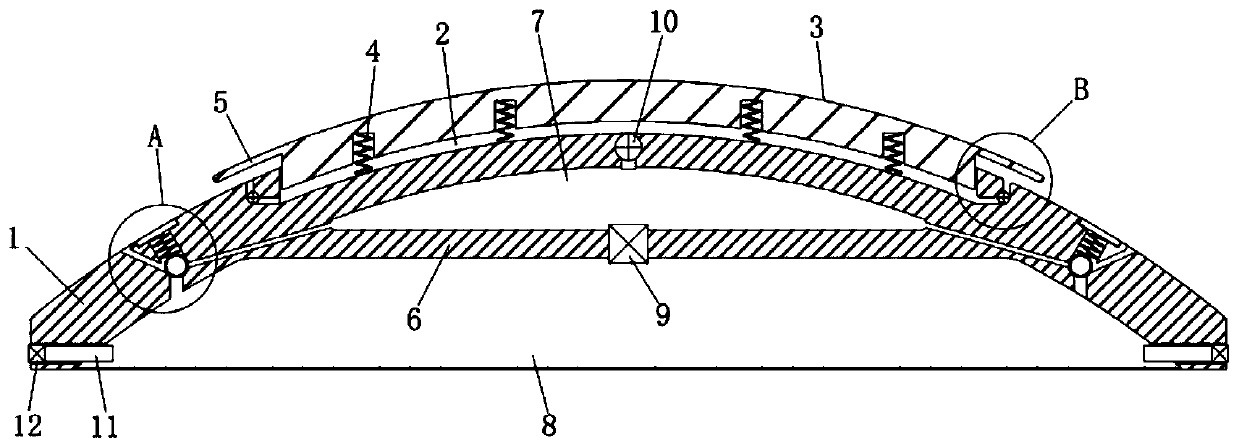
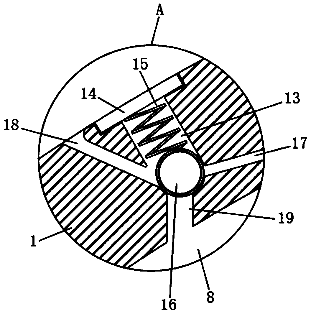
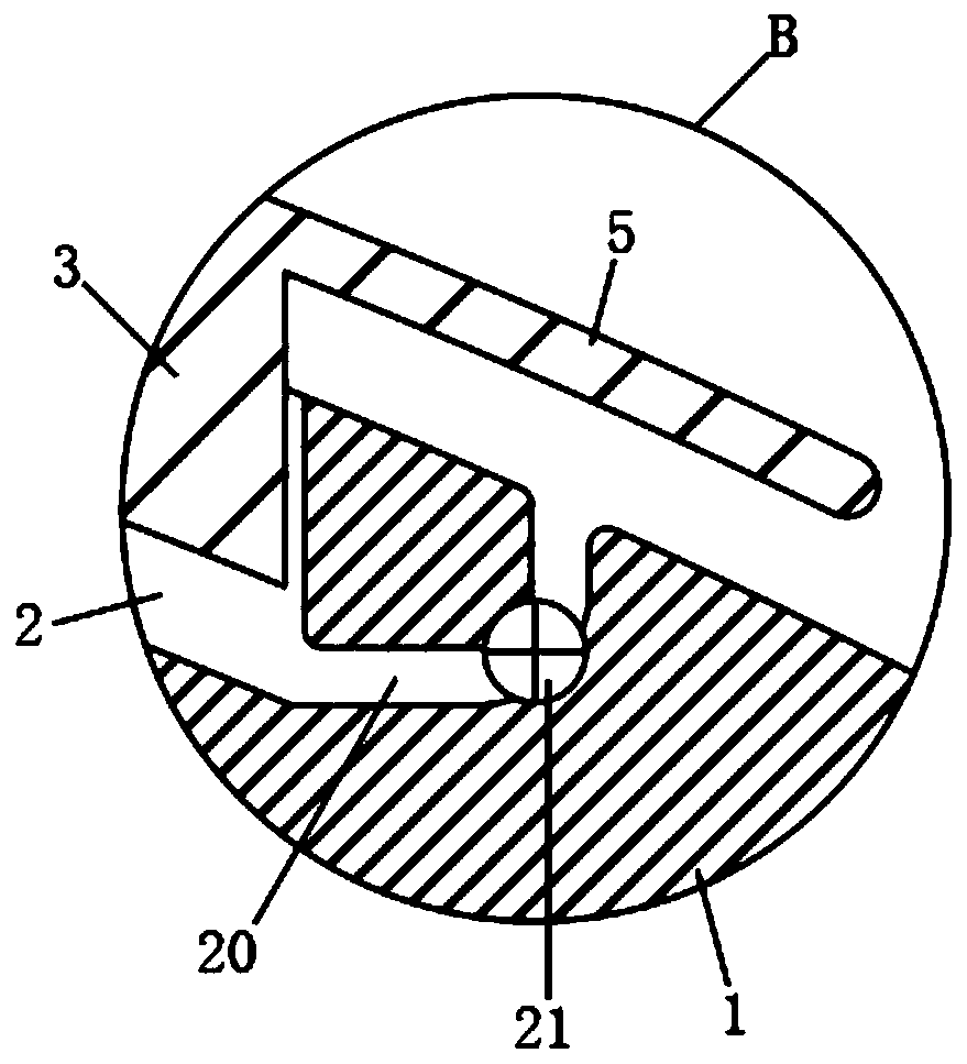
The invention discloses a deceleration strip for a sponge city. An arc-shaped main body is included. An inner portion of the arc-shaped main body is divided into a gas collection cavity and a water collection cavity through a partition plate. The gas collection cavity is positioned above the water collection cavity; the gas collection cavity is connected with the water collection cavity through apressure valve; a mounting groove is arranged in an upper part of the main body; a pressing plate is elastically mounted in the mounting groove; the mounting groove is connected with the gas collection cavity through a first one-way valve; a plurality of micro spray heads are fixedly mounted at the bottoms of the two sides of the main body; the micro spray heads are connected with the water collection cavity through a water outlet pipe; and the water collection cavity is connected with the outside through a temperature control valve, the temperature control valve comprises a memory alloy spring and a ball, a connecting cavity is arranged in the main body, the gas collection cavity is connected with the connecting cavity through a first air hole, the water collection cavity is connected with the connecting cavity through a water inlet hole, and a collecting hole connected with the connecting cavity is arranged in the surface of the main body. An effect of rainwater collection and reutilization is achieved, and a design concept of the sponge cities in the new era is met.

Description

technical field [0001] The invention belongs to the technical field of speed bumps, in particular to a speed bump for a sponge city. Background technique [0002] Sponge city is a new generation of urban stormwater management concept, which means that the city can be like a sponge and has good flexibility in adapting to environmental changes and responding to natural disasters caused by rainwater; under the new situation, sponge city is to promote green building Construction, low-carbon city development, and the innovative performance of smart city formation are the organic combination of modern green new technologies and various factors such as society, environment, and humanities under the background of the characteristics of the new era. [0003] Speed ​​bumps are also called deceleration ridges, which are traffic facilities installed on the road to slow down passing vehicles. They are generally installed on highway crossings, industrial and mining enterprises, schools, r...

Claims


Application Information

Patent Timeline
Patent Type & Authority Applications(China)
IPC IPC(8): E01F9/529E03B3/02E01C11/24
CPCE01C11/24E03B3/02E01F9/529Y02A20/108
Inventor 周友金
Owner 赵伯阳
Learn More