Safety plug

A technology of safety plugs and shells, which is applied in the direction of contact parts, electrical components, and devices to prevent contact with live contacts, etc., which can solve the problems of unsafe plugs and easy loosening, so as to avoid heating and short circuits, stabilize response temperature, and avoid overheating too high effect

Active Publication Date: 2020-08-14
常熟市华岳触控科技有限公司
View PDF11 Cites 5 Cited by
  • Summary
  • Abstract
  • Description
  • Claims
  • Application Information

AI Technical Summary

Problems solved by technology

[0004] The purpose of the present invention is to solve the problem that the plug

Method used


Image

  • Safety plug
  • Safety plug
  • Safety plug

Examples


Example Embodiment

[0020] Example 1

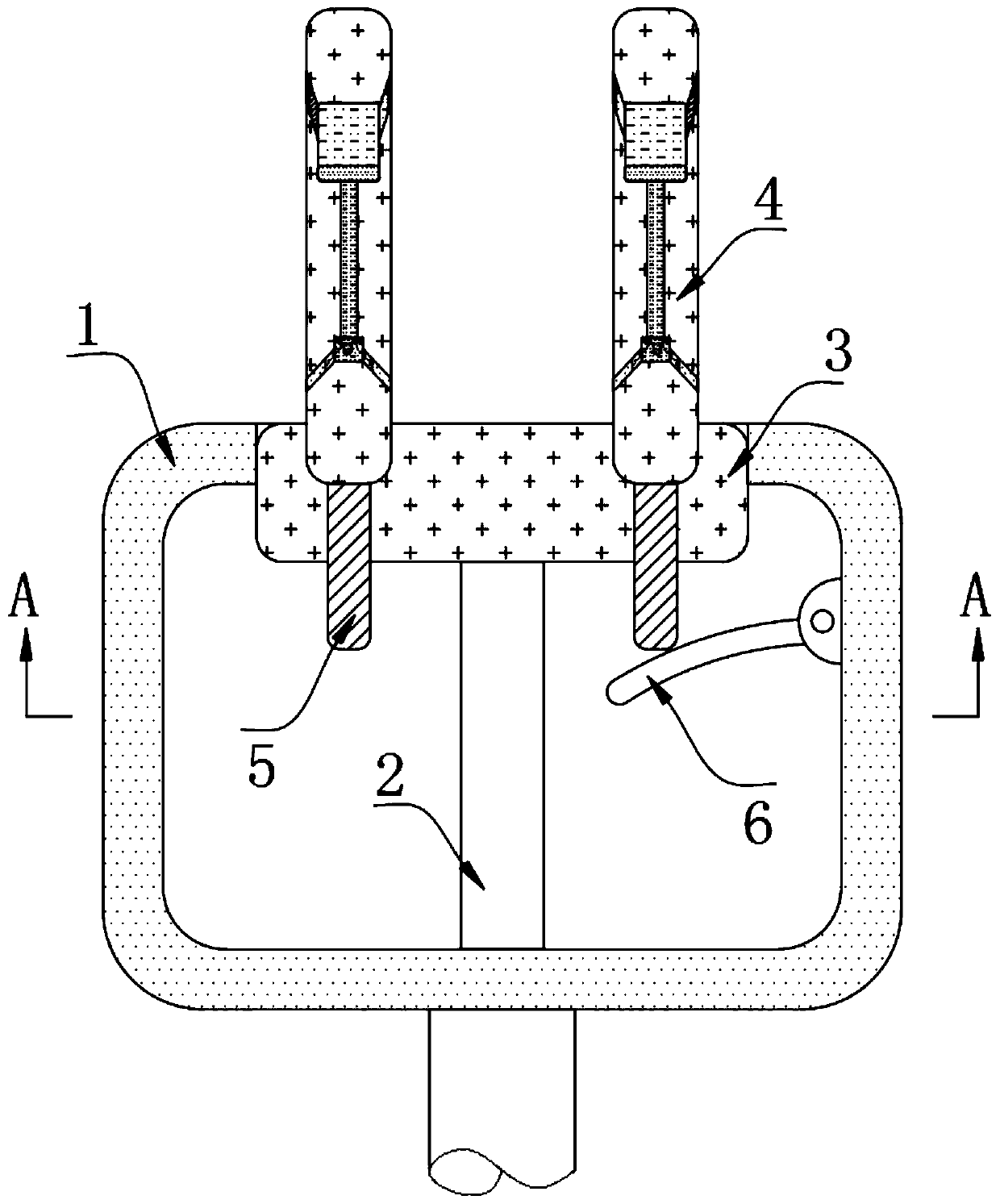
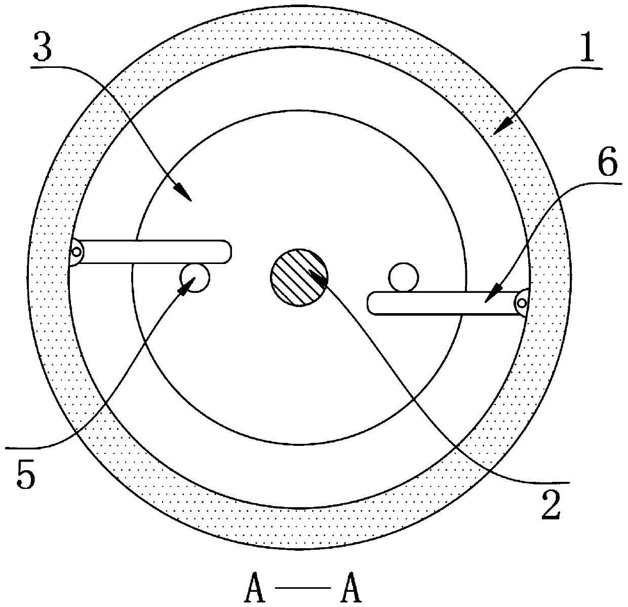
[0021] Reference Figure 1-3 , A safety plug includes a housing 1. The inner wall of the housing 1 is rotatably connected with a rotating shaft 2 through a torsion spring. The upper end of the rotating shaft 2 is fixed with a turntable 3, and the turntable 3 is connected to the side wall of the housing 1 for rotation. The upper end of the turntable 3 is inserted There are two symmetrical connection posts 4, and the inside of the two connection posts 4 is equipped with an anti-drop mechanism. The ends of the two connection posts 4 close to the rotating shaft 2 are fixed with a conductive post 5 that penetrates the turntable 3, and the housing 1 The inner wall is rotatably connected with the power-off poles 6 which are opposed to the two conductive poles 5 through a torsion spring.

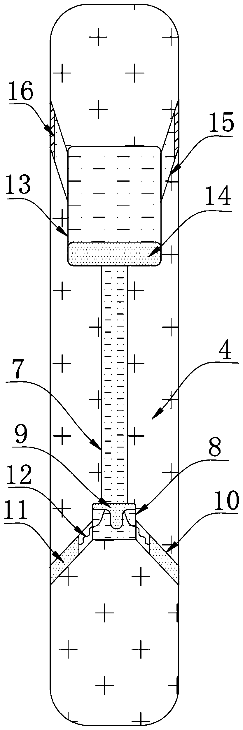
[0022] The anti-dropping mechanism includes an expansion cavity 7 opened inside the electrical connection column 4, and the expansion cavity 7 is provided with a retaining slot 8 on o...

Example Embodiment

[0028] Example 2

[0029] Reference Figure 4 , A safety plug includes a housing 1, the inner wall of the housing 1 is rotatably connected with a shaft 2 through a torsion spring, the upper end of the shaft 2 is fixed with a turntable 3, the turntable 3 is rotatably connected with the side wall of the housing 1, and the upper end of the turntable 3 is inserted There are two symmetrical connection posts 4, and the inside of the two connection posts 4 is equipped with an anti-drop mechanism. The ends of the two connection posts 4 close to the shaft 2 are fixed with a conductive post 5 that penetrates the turntable 3, The inner wall is rotatably connected with the power cut-off pillars 6 that are opposed to the two conductive pillars 5 through a torsion spring.

[0030] The anti-dropping mechanism includes an expansion cavity 7 opened inside the electrical connection column 4, and the expansion cavity 7 is provided with a retaining slot 8 on one side close to the housing 1. The interi...


PUM


Abstract

The invention discloses a safety plug. The safety plug comprises a shell, the inner wall of the shell is rotationally connected with a rotating shaft through a torsional spring; a turntable is fixed at the upper end of the rotating shaft; the turntable is rotatably connected with the side wall of the shell in a penetrating manner; and two symmetrical power connection columns are inserted into theupper end of the turntable, anti-falling mechanisms are arranged in the two power connection columns correspondingly, conduction columns penetrating through the turntable are fixed to the ends, closeto the rotating shaft, of the two power connection columns correspondingly, and the inner wall of the shell is rotationally connected with power-off columns abutting against the two conduction columnsthrough torsional springs correspondingly. The safety plug has the advantages that the volume change is caused by the form change of electrorheological fluid in the expansion cavity after the electrorheological fluid is electrified; a push plate and a push block are pushed, so that a clamping block is moved out of a sliding groove to form a protrusion outwards to effectively prevent the power connection columns from moving, the power connection columns cannot be separated from a socket, the plug is prevented from being separated from the socket in the power utilization process, the plug can be pulled by the outer wall to a certain extent, and a user does not need to worry about that the plug falls off easily.

Description

Technical field [0001] The invention relates to the technical field of plugs, in particular to a safety plug. Background technique [0002] The connector of general electronic products and electrical appliance pins are called plugs. Household AC power plugs and sockets have male connectors protruding in the shape of rods or copper plates, which are physically inserted into socket-type power sockets with slots or recesses. [0003] The plug is generally used in conjunction with the socket to complete the power supply to the electrical appliance. After the plug of the electrical appliance is inserted into the jack, it directly contacts the metal reed in the socket that is connected to the zero live wire. After the reed has been used for a long time Poor contact is easy to occur, which leads to instability or even short circuit in the electrical connection process, and the existing plugs will heat up after long-term use, especially when the power of external electrical appliances is h...

Claims


Application Information

Patent Timeline
IPC IPC(8): H01R13/04H01R13/639H01R13/193H01R13/44H01R13/713
CPCH01R13/04H01R13/193H01R13/44H01R13/639H01R13/713H01R13/7132
Inventor 杨娟齐杰
Owner 常熟市华岳触控科技有限公司
Why Eureka
Try Eureka