Traction device convenient for trailer
A technology of traction device and trailer, which is applied in the direction of traction connectors, vehicle parts, transportation and packaging, etc. It can solve the problems that the longitudinal traction main pipe cannot be retracted, and cannot meet the use of multiple types of vehicle trailers, so as to achieve the effect of easy traction
- Summary
- Abstract
- Description
- Claims
- Application Information
AI Technical Summary
Problems solved by technology
Method used
Image
Examples
specific Embodiment approach 1
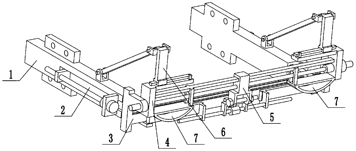
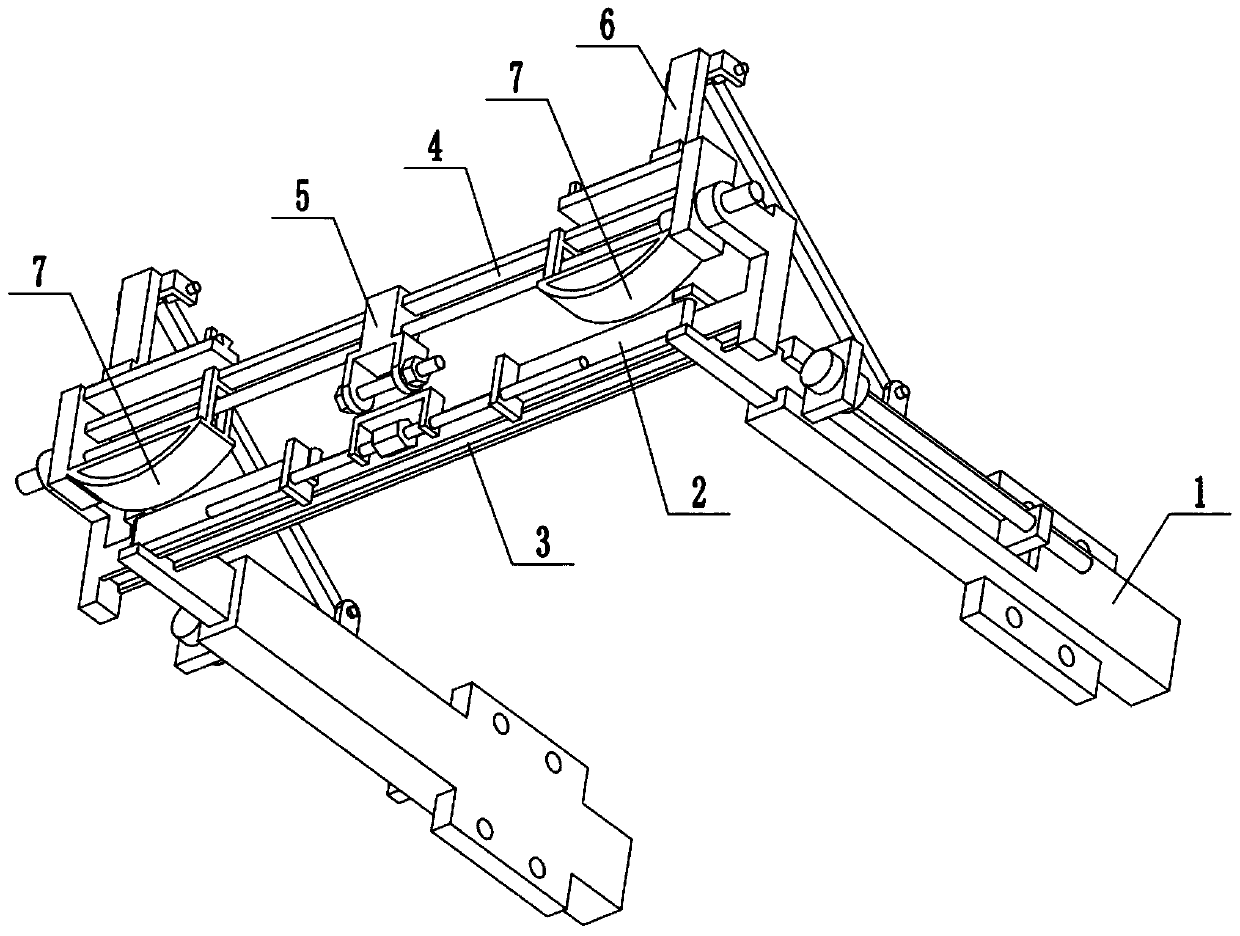
[0027] Combine below Figure 1-7 Describe this embodiment, a kind of traction device that is convenient to trailer, comprises traction fixing frame 1, telescopic frame 2, front beam member 3, traction member rotating seat 4, traction fixing member 5, rotating drive member 6 and anti-collision buffer member 7, Two traction mounts 1 are provided, and the two ends of the telescopic mount 2 are connected with the two traction mounts 1 respectively. On the front cross member 3, the traction fixing part 5 is matched and connected on the traction part rotating seat 4, and there are two rotating driving parts 6, and one end of the two rotating driving parts 6 is respectively arranged on two traction fixing mounts 1, and the two The other end of each rotating driving part 6 is respectively movably connected with the two ends of the traction part rotating seat 4, and two anti-collision buffer parts 7 are symmetrically arranged on the lower end of the traction part rotating seat 4. When...
specific Embodiment approach 2
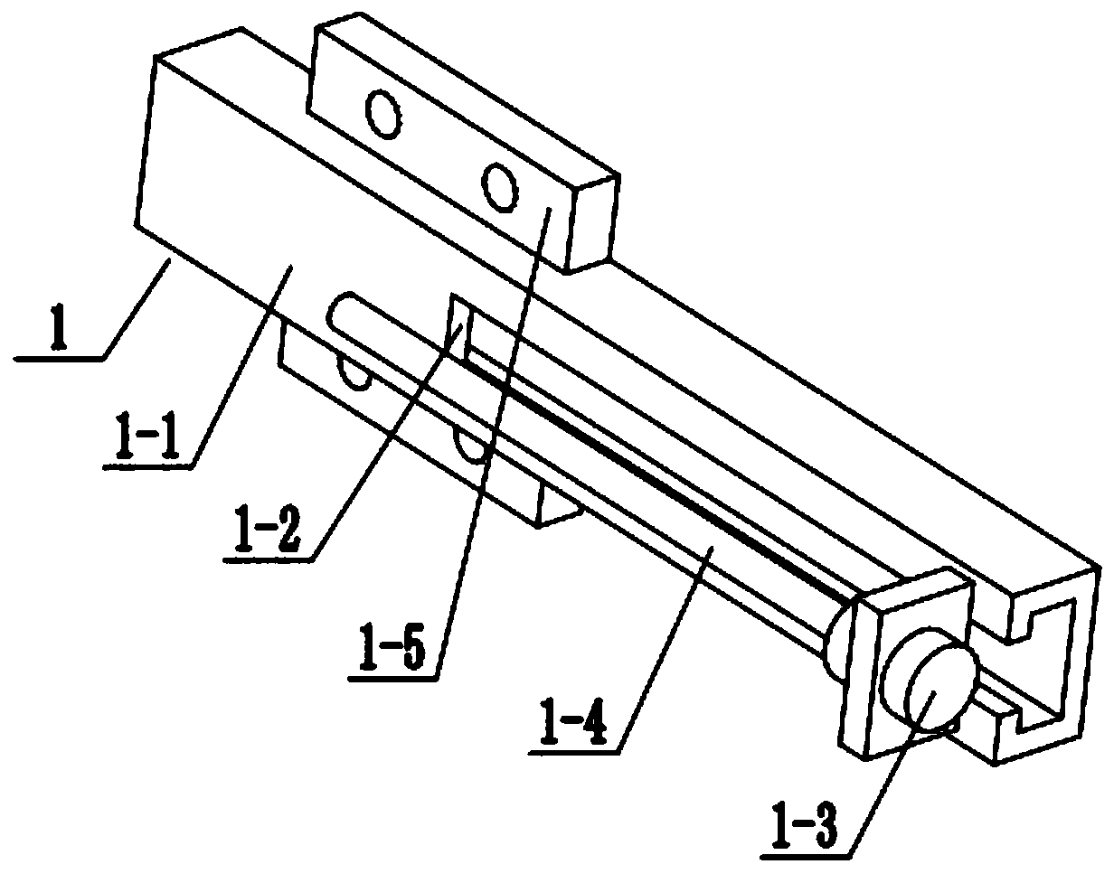
[0029] Combine below Figure 1-7To illustrate this embodiment, the traction fixture 1 includes a hollow frame 1-1, a side chute 1-2, a first motor 1-3, a lead screw 1-4 and a screw seat 1-5; the hollow frame 1-1 The outer end is provided with a side chute 1-2, the first motor 1-3 is fixedly connected to the hollow frame 1-1 through the motor frame, and the output shaft of the first motor 1-3 is connected to the lead screw 1-4 through a coupling , The two ends of the hollow frame 1-1 are respectively provided with a screw seat 1-5; the telescopic frame 2 is connected with the hollow frame 1-1. The hollow frame 1-1 is fixed on the tail of the tractor by inserting screws into the two screw seats 1-5. After the first motor 1-3 is started, the lead screw 1-4 is driven to rotate, and the lead screw 1-4 drives the telescopic frame 2 Extend or retract.
specific Embodiment approach 3
[0031] Combine below Figure 1-7 To illustrate this embodiment, the telescopic frame 2 includes a screw 2-1, a two-way screw 2-2, a screw frame 2-3, a linkage plate 2-4, a telescopic frame 2-5, a groove block 2-6, a front Through groove 2-7 and projection 2-8; screwing part 2-1 is fixedly connected in the middle part of two-way screw rod 2-2, and two-way screw rod 2-2 is rotatably connected on the screw rod frame 2-3, and the two-way screw rod 2-2 The two ends are respectively connected to a linkage plate 2-4 through thread fit, and the outer ends of the two telescopic frames 2-5 are respectively fixedly connected to a groove block 2-6; the telescopic frame 2-5 is connected to the hollow frame 1-1 with sliding fit Inside, the groove block 2-6 is slidably connected in the side chute 1-2, and the groove block 2-6 is connected on the lead screw 1-4 through thread fit; the front ends of the two telescopic frames 2-5 are respectively provided with a front Through slot 2-7, the out...
PUM
 Abstract
Description
Claims
Application Information
 - R&D
- Intellectual Property
- Life Sciences
- Materials
- Tech Scout
- Unparalleled Data Quality
- Higher Quality Content
- 60% Fewer Hallucinations
Browse by: Latest US Patents, China's latest patents, Technical Efficacy Thesaurus, Application Domain, Technology Topic, Popular Technical Reports.
© 2025 PatSnap. All rights reserved.Legal|Privacy policy|Modern Slavery Act Transparency Statement|Sitemap|About US| Contact US: help@patsnap.com


