Pop-up winding device

A wire winding device and a pop-up technology, applied in the field of the pop-up wire winding device, can solve the problems of loose and deformed wire coils, difficult transportation, and increased labor intensity of workers, so as to reduce labor intensity, fall off easily, and fall off easily and conveniently. Effect

Active Publication Date: 2020-09-01
江苏亚盛金属制品有限公司
View PDF8 Cites 0 Cited by
  • Summary
  • Abstract
  • Description
  • Claims
  • Application Information

AI Technical Summary

Problems solved by technology

[0002] Existing wires such as wire ropes, cables or high wires are often wound on I-shaped wheels when they are sold, which increases the difficulty of transportation. At the same time, if the customer demand is small, or the company uses it as an exhibition model When it is used, it is often not needed, and it needs to be rolled into a small roll without a central axis for packaging. The existing operation method is to use each I-shaped wheel, and the side plate at one end of the I-shaped wheel is fixed with bolts. It is detachably installed on the I-shaped wheel. When the I-shaped wheel is rolled to the specified length, during the disassembly process of the I-shaped wheel with this structure, it is necessary to remove the side plate first, and then remove the wire on the I-shaped wheel. It is difficult to disassemble the wire wound on the I-shaped wheel, and the manual disassembly will often cause the wire coil to loosen and deform, and it will also increase the labor intensity of the workers.

Method used


Image

  • Pop-up winding device
  • Pop-up winding device

Examples


Embodiment Construction

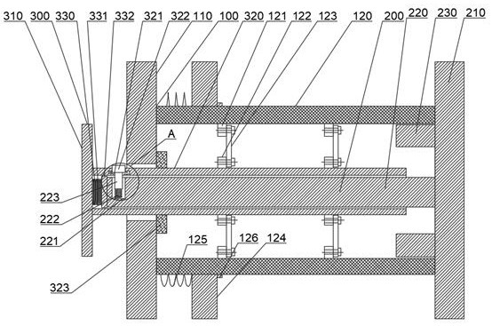
[0017] In order to have a further understanding of the purpose, structure, features, and functions of the present invention, the following detailed descriptions are provided in conjunction with the embodiments. Such as figure 1 As shown, a pop-up type winding device includes an outer core 100, an inner core 200 and a rotating shaft 300. The outer core 100 includes a first side plate 110 and a coil fixed on the first side plate. Wire barrel 120, the inner barrel core 200 includes a second side plate 210, a central shaft 220 and a support plate 230 fixed on the second side plate, and the central shaft 220 and the support plate are placed on the bobbin In 120 , the support plate 230 is cylindrical, and the outer wall of the support plate 230 is attached to the inner wall of the reel 120 to support the reel 120 . The second side plate 210 is located at an end of the reel 120 away from the first side plate 110 ;

[0018] The rotating shaft 300 includes a rotating handle 310 and a...


PUM


Abstract

The invention provides a pop-up winding device. The pop-up winding device comprises an outer cylinder core, an inner cylinder core and a rotating shaft, wherein the outer cylinder core comprises a first side plate and a winding cylinder fixed to the first side plate, the inner cylinder core comprises a second side plate, a center shaft and a supporting plate, the center shaft and the supporting plate are fixed to the second side plate, the center shaft and the supporting plate are arranged in the winding cylinder, and the second side plate is located at the end, away from the first side plate,of the winding cylinder; and the rotating shaft comprises a rotating handle and a main body shaft fixed to the rotating handle, the main body shaft is a hollow shaft, and the main body shaft penetrates through the first side plate to enter the winding cylinder and is arranged on the periphery of the center shaft in a sleeving mode. According to the pop-up winding device, a steel wire on a spool is automatically popped up and released from the spool, so that the labor intensity of workers is reduced, and the phenomenon of deformation when the wire is released from the spool is reduced.

Description

technical field [0001] The invention relates to the field of wire winding, in particular to a pop-up type winding device. Background technique [0002] Existing wires such as wire ropes, cables or high wires are often wound on I-shaped wheels when they are sold, which increases the difficulty of transportation. At the same time, if the customer demand is small, or the company uses it as an exhibition model When it is used, it is often not needed, and it needs to be rolled into a small roll without a central axis for packaging. The existing operation method is to use each I-shaped wheel, and the side plate at one end of the I-shaped wheel is fixed with bolts. It is detachably installed on the I-shaped wheel. When the I-shaped wheel is rolled to the specified length, during the disassembly process of the I-shaped wheel with this structure, it is necessary to remove the side plate first, and then remove the wire on the I-shaped wheel. It is difficult to disassemble the wire ro...

Claims


Application Information

Patent Timeline
Patent Type & Authority Applications(China)
IPC IPC(8): B65H67/04
CPCB65H67/0411B65H2701/31
Inventor 周江曹光明蒋红俊蒋红兵陆树骏周海东
Owner 江苏亚盛金属制品有限公司
Why Eureka
Try Eureka