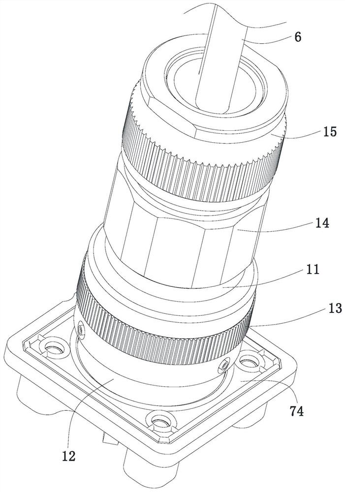
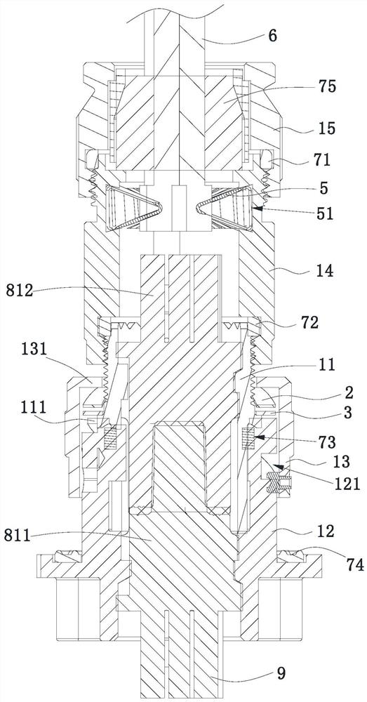
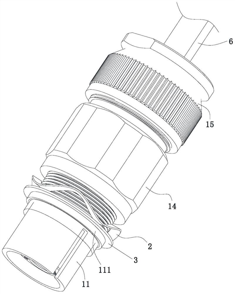
Shielded connector

A connector and shielded technology, which is applied in the field of shielded connectors, can solve the problem of weak conductive connection of the housing

Active Publication Date: 2021-11-16
顺科智连技术股份有限公司
View PDF10 Cites 0 Cited by
  • Summary
  • Abstract
  • Description
  • Claims
  • Application Information

AI Technical Summary

Problems solved by technology

[0003] The purpose of the present invention is to provide a shielded connector to solve the technical problem of weak conductive connection between shells existing in the prior art

Method used


Image

  • Shielded connector
  • Shielded connector
  • Shielded connector

Examples


Embodiment Construction

[0027] In order to make the technical problems, technical solutions and beneficial effects to be solved by the present invention clearer, the present invention will be further described in detail below in conjunction with the accompanying drawings and embodiments. It should be understood that the specific embodiments described here are only used to explain the present invention, not to limit the present invention.

[0028] It should be noted that when an element is referred to as being “fixed” or “disposed on” another element, it may be directly on the other element or be indirectly on the other element. When an element is referred to as being "connected to" another element, it can be directly connected to the other element or indirectly connected to the other element.

[0029] It is to be understood that the terms "length", "width", "top", "bottom", "front", "rear", "left", "right", "vertical", "horizontal", "top" , "bottom", "inner", "outer" and other indicated orientations...


PUM


Abstract

The present invention relates to the technical field of connectors, and provides a shielded connector, comprising a first conductive cylinder, a second conductive cylinder detachably sleeved on the first conductive cylinder, sleeved and slidably mounted on the The third conductive cylinder on the first conductive cylinder, the male terminal disposed in the first conductive cylinder, the female terminal disposed in the second conductive cylinder, and the cable conductively connected to the male terminal; the second conductive cylinder The body is detachably fixed on the third conductive cylinder, and the male terminal is inserted on the female terminal; the first conductive cylinder is provided with a first conductive stopper, and the third conductive cylinder is provided with a second conductive stopper part, a conductive elastic piece is sandwiched between the first conductive stop part and the second conductive stop part; the shielded wire in the cable is electrically connected to the first conductive cylinder. The first conductive cylinder and the second conductive cylinder are conductively connected, so that the second conductive cylinder can also be shielded by the shielding wire.

Description

technical field [0001] The invention belongs to the technical field of connectors, and more specifically relates to a shielded connector. Background technique [0002] Connectors (connectors: used to turn on / off circuits for current transfer; connectors are usually female terminals and male terminals are turned on / off by plugging in and out) are widely used in modern electromechanical equipment. In order to ensure the safety of the connector, grounding is sometimes required between the shells. Usually, screws are directly used to fix adjacent shells to achieve conductive connection, but the two shells fixed by screws are very weak. Contents of the invention [0003] The purpose of the present invention is to provide a shielded connector to solve the technical problem in the prior art that the conductive connection between shells is not firm. [0004] In order to achieve the above object, the technical solution adopted by the present invention is to provide a shielded conn...

Claims


Application Information

Patent Timeline
Patent Type & Authority Patents(China)
IPC IPC(8): H01R13/6585H01R13/6591H01R13/6593H01R13/648H01R13/623H01R24/86
CPCH01R13/623H01R13/648H01R13/6585H01R13/6591H01R13/6593H01R24/86
Inventor 曾志坚罗伟康邹太和
Owner 顺科智连技术股份有限公司
Why Eureka
Try Eureka