Self-excited oscillation annular jet stirring system

A technology of annular jet and stirring system, which is applied in chemical/physical/physical-chemical fixed reactors, chemical/physical/physical-chemical processes, chemical instruments and methods, etc., can solve problems such as difficult sealing of motor shafts, and achieve a solution to the problem of sealing Difficulty, improve stirring efficiency, improve the effect of increasing mixing effect

Active Publication Date: 2020-09-08
TAIYUAN UNIV OF TECH
View PDF7 Cites 1 Cited by
  • Summary
  • Abstract
  • Description
  • Claims
  • Application Information

AI Technical Summary

Problems solved by technology

[0003] In order to solve the problem that traditional stirring equipment is difficult to seal due to the motor shaft, the present invention provides a self-excited oscillating annular jet stirring system

Method used


Image

  • Self-excited oscillation annular jet stirring system
  • Self-excited oscillation annular jet stirring system
  • Self-excited oscillation annular jet stirring system

Examples


Embodiment 1

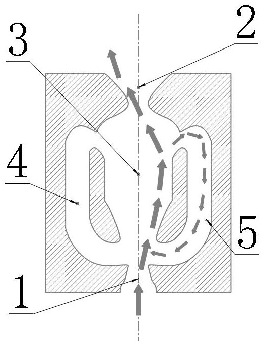
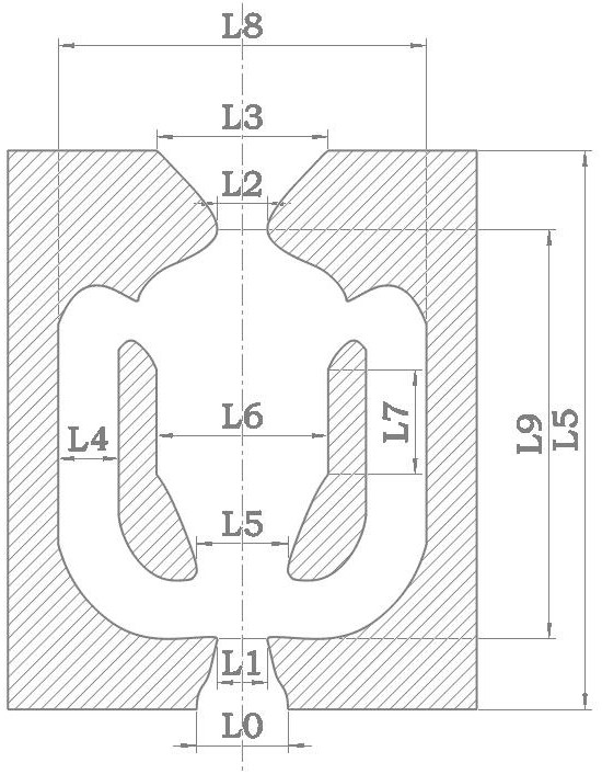
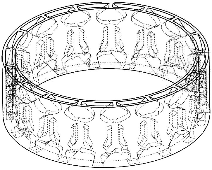
[0036] Oscillating jet unit ( figure 1 ) is a self-excited oscillating annular jet stirring device ( image 3 ) basic unit, including a main chamber 3 and interconnected water outlet 2 and water inlet 1; main chamber 3 and corresponding left feedback channel 4 and right feedback channel connection 5. For the size parameters of the oscillating jet unit, see figure 2 . The water inlet is roughly an isosceles trapezoid with a ratio of upper and lower bases (L1:L0) of 1:3 to 2:3, and the angle between the two waists is 60°. The water outlet is an approximately isosceles trapezoid with a bottom-to-bottom ratio (L2:L3) of 1:5-2:5. The isosceles trapezoid is connected to the main chamber 3, and the angle between the two sides is 90°. The ratio of the length L9 of the main chamber from the connection of the water inlet 1 to the connection of the water outlet 2 to the size of the water inlet L0 is 4:1-6:1. The ratio of the width of the main chamber where the section size remains c...

Embodiment 2

[0043] The difference between embodiment 2 and embodiment 1 is that, as Figure 8 As shown, the structure of the basic unit of jet oscillation in Embodiment 2 remains unchanged, but the annular cylinder formed by several basic units in Embodiment 1 is changed into a conical surface. This change requires each basic unit to form a certain curved arc and form a closed loop. As a result, the jets of each basic unit sweep clockwise and counterclockwise alternately on the cone surface, which enhances the intensity of the large-scale jet movement in the middle area. At the same time, the sweeping jet cone surface and the inner wall cylinder of the stirred tank maintain an appropriate space interval, which is beneficial to the inner circulation of the large-scale jet movement inside the stirred tank. It also further enhances the applicability.

[0044] In conjunction with the first embodiment, the principles of the present invention are explained as follows:

[0045] The flow princi...


PUM


Abstract

The invention belongs to the technical field of stirring, and particularly relates to a self-excited oscillation annular jet stirring system. The problem that the traditional stirring equipment is difficult to seal due to a motor shaft is solved. The stirring system comprises a stirring kettle shell, an oscillation jet annular stirring device, a medium inlet, a supernatant outlet, a jet liquid pipeline, a diaphragm pressure pump and a medium outlet, wherein the oscillation jet annular stirring device is arranged in the stirring kettle shell, the medium inlet is formed in the top of the stirring kettle shell, the supernatant outlet is formed in one side of the upper part of the stirring kettle shell, the medium outlet is formed in the lower part of the stirring kettle shell, and the supernatant outlet is connected to an inlet of the oscillation jet annular stirring device through the diaphragm pressure pump andthe jet liquid pipeline. According to the self-excited oscillation annular jet flow stirring device, no paddle or blade is used, strong shear flow cannot be generated, and flora and molecular structures of related organic solutions cannot be damaged.

Description

technical field [0001] The invention belongs to the technical field of stirring, in particular to a self-excited oscillating annular jet stirring system. Background technique [0002] In organic solutions containing biological fungi or other unsuitable to withstand strong shear, there are substances such as cell membranes, long-chain polymers, etc., and these solutions are often accompanied by stirring in the process of biological treatment or related chemical reactions . Currently commonly used stirring equipment includes mechanical stirring devices and jet stirring devices. Most of the mechanical stirring devices have complex structures. When the motor drives the stirring blades / stirring paddles to rotate at high speed, it will bring strong shear flow to the local area of ​​the solution, which is easy to destroy the activity of the bacterial flora or the long-chain molecular structure of the related organic solution, and it is difficult to meet the requirements. At the s...

Claims


Application Information

Patent Timeline
Patent Type & Authority Applications(China)
IPC IPC(8): B01J19/24B01J19/00
CPCB01J19/0006B01J19/0053B01J19/2455B01J2219/00164
Inventor 田海平李芬张一田金梓谦周谧
Owner TAIYUAN UNIV OF TECH
Why Eureka
Try Eureka