
A rotating lens and projection equipment

A technology of rotating prisms and lenses, which is applied in the field of lenses, can solve problems such as uneconomical and inconvenient, and achieve the effects of reliable performance, simple system and convenient use

Active Publication Date: 2021-06-22
SICHUAN CHANGHONG ELECTRIC CO LTD
View PDF0 Cites 0 Cited by
  • Summary
  • Abstract
  • Description
  • Claims
  • Application Information

AI Technical Summary

Problems solved by technology

However, ordinary projection products are difficult to place stably in multiple directions, and often need to use additional brackets to achieve it, which is uneconomical and inconvenient

Method used


Image

  • A rotating lens and projection equipment
  • A rotating lens and projection equipment
  • A rotating lens and projection equipment

Examples


Embodiment 1

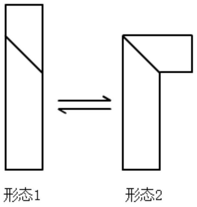
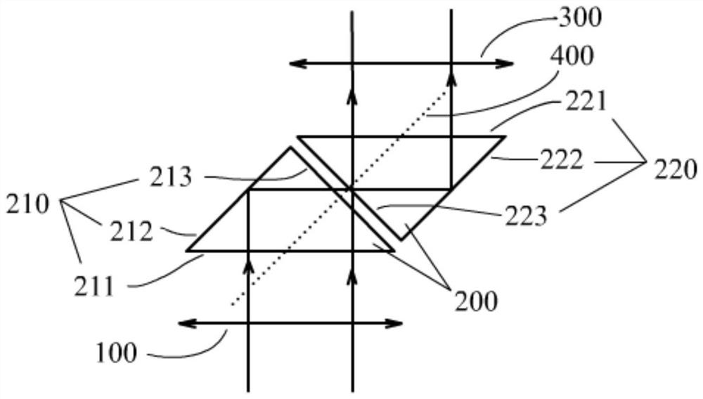
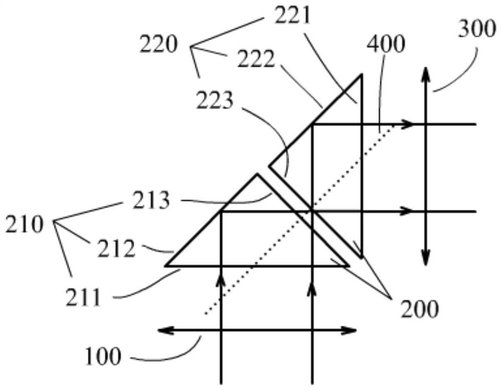
[0023] The present invention proposes a rotating lens, which includes a lens front group 100, a rotating prism group 200, and a lens rear group 300, which sequentially pass through the lens front group 100, the rotating prism group 200, and the lens rear group 300 along the direction of light propagation; The rotating prism group 200 is used to change the direction of the outgoing light. The lens front group 100 is used to receive the light beam to be imaged; the rotating prism group 200 is used to change the outgoing direction of the light beam to be imaged; the rear lens group 300 is used to output the light beam to be imaged after changing the outgoing direction. The rotating lens is mainly used for imaging and magnification.

[0024] The rotating prism group 200 includes an isosceles right-angle prism 1210 and an isosceles right-angle prism 2220, a right-angle surface 213 of the isosceles right-angle prism 1210 fits a right-angle surface 223 of the isosceles right-angle pr...


PUM


Abstract

The invention discloses a rotating lens and projection equipment, belonging to the technical field of lenses. The present invention proposes a rotating lens, which includes a lens front group, a rotating prism group, and a lens rear group, which sequentially pass through the lens front group, rotating prism group, and lens rear group along the light propagation direction; the lens front group, lens The rear group is mainly used for imaging and magnification; the rotating prism group is used for changing the direction of outgoing light. The rotating lens of the present invention can change the direction of outgoing light, and the projection device using the rotating lens of the present invention can change the projection angle and picture position without changing the placement method, such as projecting on side walls and ceiling walls. The system of the invention is simple, easy to use and reliable in performance.

Description

technical field [0001] The invention relates to the field of lens technology, and more specifically relates to a rotating lens and projection equipment. Background technique [0002] Projection has been widely used in ordinary homes, office conference rooms, educational institutions, and entertainment venues. [0003] The projection products on the market have only one lens and the direction of the outgoing light is unique. If you want to adjust the direction of the outgoing light, such as first projecting on the side wall and then changing the projection to the ceiling, you need to change the placement angle of the projection product and the direction of the light. However, ordinary projection products are difficult to place stably in multiple directions, and often require additional brackets to achieve this, which is uneconomical and inconvenient. [0004] Therefore, there is a need for a lens and a projection product that can greatly change the direction of outgoing lig...

Claims


Application Information

Patent Timeline
Patent Type & Authority Patents(China)
IPC IPC(8): G02B5/04G02B7/18G02B1/11G03B21/14
CPCG02B5/04G02B7/1805G02B1/11G03B21/14
Inventor 蔡静
Owner SICHUAN CHANGHONG ELECTRIC CO LTD
Learn More