Auxiliary turnover device for nursing
A flap and front flap technology, which is applied in medical science, hospital beds, hospital equipment, etc., can solve the problems that the nursing bed cannot sit up and defecate simultaneously, and it is inconvenient to turn over, so as to solve the problems of single function and cumbersome operation , the effect of preventing bedsores
- Summary
- Abstract
- Description
- Claims
- Application Information
AI Technical Summary
Problems solved by technology
Method used
Image

Examples
Embodiment 1
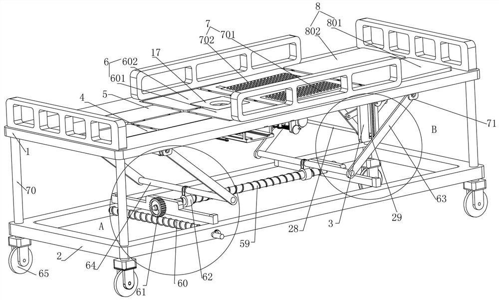
[0046] Embodiment 1, the auxiliary turning device for nursing includes an upper bed body 1 and a lower bed body 2. The upper bed body 1 is installed on the lower bed body 2 by sliding up and down, and the upper bed body 1 can slide up and down on the lower bed body 2 to adjust the upper bed when in use. The height of the body 1, the upper bed body 1 is provided with a through hole slot, the upper bed body 1 is hinged with a second left sliding plate 5 that slides up and down in the through hole slot, and the second left sliding plate 5 can be used when in use. Slide up and down in the through hole groove on the upper bed body 1, the left end of the second left sliding plate 5 is hinged with the first left sliding plate 4 that slides up and down in the through hole groove. The first left sliding plate 4 slides up and down, the upper bed body 1 is hinged with a front and rear flap 6 located at the right end of the second left sliding plate 5, and the upper end of the upper bed bo...
Embodiment 2
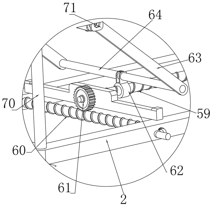
[0054] Embodiment 2, on the basis of Embodiment 1, the first link mechanism is composed of a first left rotation rod 9, a second left rotation rod 10 and a third left rotation rod 12. The lower end of the left sliding plate 4 is hinged with a first left rotating rod 9, the other end of the first left rotating rod 9 is hinged on one end of the third left rotating rod 12, and the second left sliding plate The lower end of 5 is hinged with a second left rotation rod 10, the other end of the second left rotation rod 10 is hinged on the middle of the third left rotation rod 12, and the other end of the third left rotation rod 12 is fixed It is installed on the first rotating column 11. When in use, the first rotating column 11 rotates and drives the third left rotating rod 12 to slide downward, and the third left rotating rod 12 carries the second left rotating rod 12 respectively. The moving rod 10 and the first left rotation rod 9 slide downward, and the second left rotation rod ...
Embodiment 3
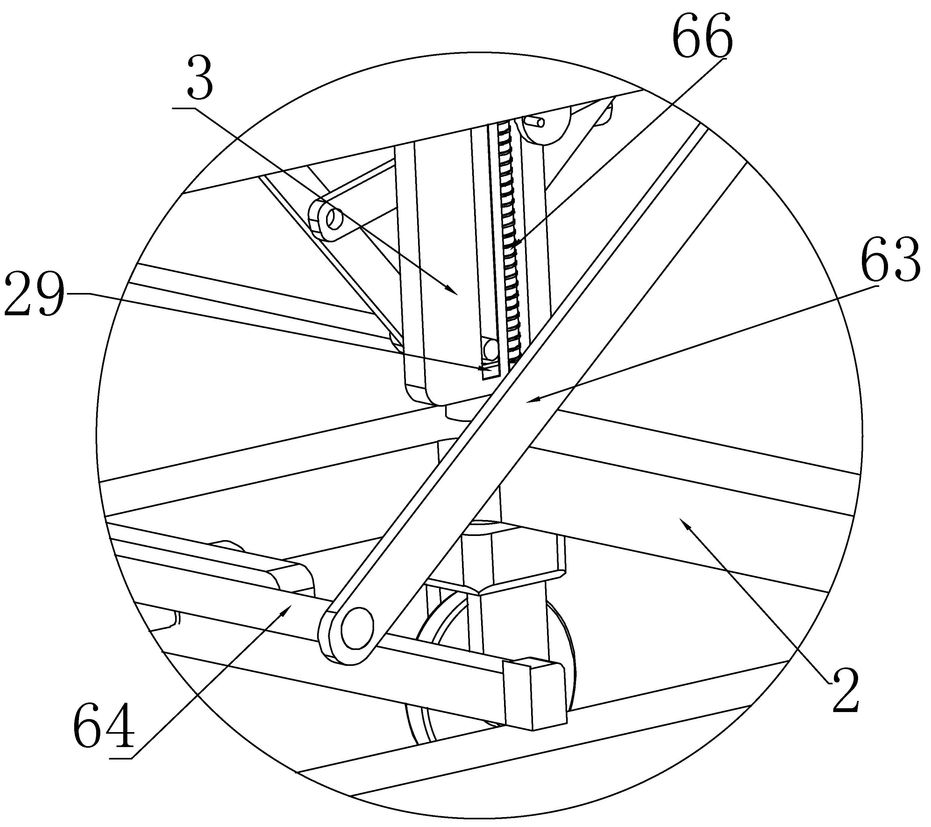
[0055]Embodiment 3, on the basis of Embodiment 1, the lower end of the upper bed body 1 is fixedly installed with a front sliding frame 30 and a rear sliding frame 31 located on the front and rear sides of the lifting plate 20, respectively. The rear side of the front sliding frame 30 The front side of the rear sliding frame 31 is arranged close to the rear side of the lifting plate 20, and the lifting plate 20 is provided with a limiting groove, and the rear side of the limiting groove is provided with a toilet 21. For the gaps with the same diameter, a sliding plate is fixedly installed at the bottom of the front sliding frame 30 and the rear sliding frame 31 respectively. A rotating handle is fixedly installed at the rear end of the rod 32, one side of the rear sliding frame 31 rotates the rear sliding frame screw 32, and the other side is fixedly installed with a guide rod parallel to the rear sliding frame screw 32. The rod 32 is coaxially threaded with a rear sliding fra...
PUM
 Abstract
Description
Claims
Application Information
 - R&D
- Intellectual Property
- Life Sciences
- Materials
- Tech Scout
- Unparalleled Data Quality
- Higher Quality Content
- 60% Fewer Hallucinations
Browse by: Latest US Patents, China's latest patents, Technical Efficacy Thesaurus, Application Domain, Technology Topic, Popular Technical Reports.
© 2025 PatSnap. All rights reserved.Legal|Privacy policy|Modern Slavery Act Transparency Statement|Sitemap|About US| Contact US: help@patsnap.com