Key board

A keyboard and keycap technology, applied in electrical components, electrical switches, circuits, etc.

Active Publication Date: 2020-09-22
QUNGUANG OPTOELECTRONICS SUZHOU
View PDF3 Cites 0 Cited by
  • Summary
  • Abstract
  • Description
  • Claims
  • Application Information

AI Technical Summary

Problems solved by technology

The keycaps sit above the base

Method used


Image

  • Key board
  • Key board
  • Key board

Examples


Embodiment Construction

[0076] Various embodiments of the present invention will be disclosed in the drawings below, and for the sake of clarity, many practical details will be described together in the following description. It should be understood, however, that these practical details should not be used to limit the invention. That is, in some embodiments of the invention, these practical details are unnecessary. In addition, for the purpose of simplifying the drawings, some conventional structures and components will be shown in a simple and schematic manner in the drawings, and the same components in different embodiments are marked with the same component symbols.

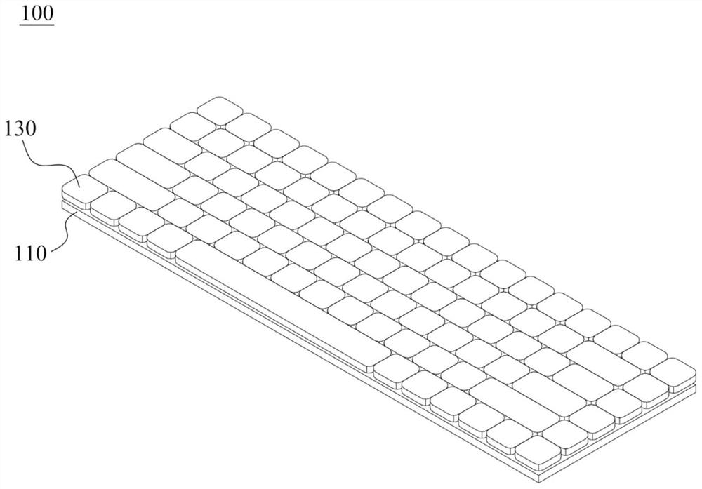
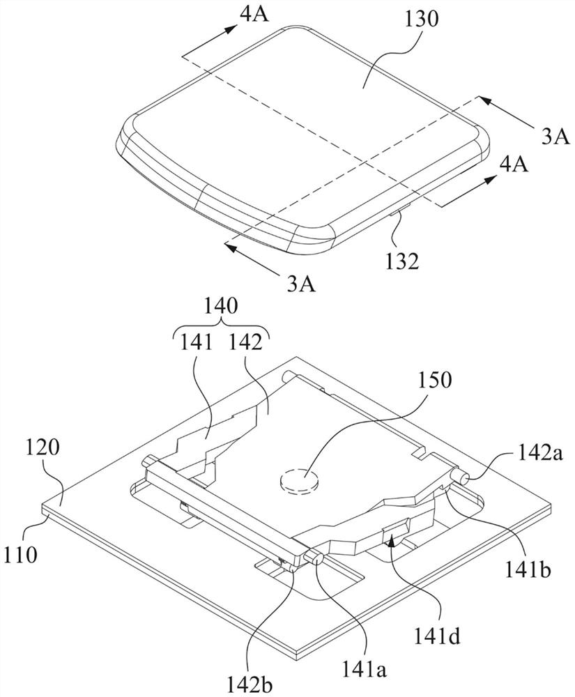
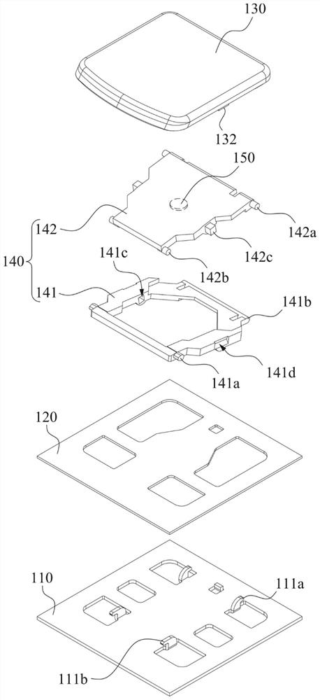
[0077] Please refer to figure 1 , Figure 2A as well as Figure 2B . figure 1 It is a perspective view of the keyboard 100 according to an embodiment of the present invention. Figure 2A It is a partial perspective view of the key device according to an embodiment of the present invention, wherein the key cap 130 is separated u...


PUM


Abstract

A keyboard comprises a base, a keycap and a connecting assembly. The key cap is located above the base. The connecting assembly is located between the base and the key cap, and comprises a first connecting part and a second connecting part which are connected with each other. The first connecting part and the second connecting part are respectively connected with the base and the keycap. And two of the base, the keycap, the first connecting part and the second connecting part are fixedly connected. When the key cap is pressed towards the base, the first connecting part and the second connecting part are elastically deformed to store elastic potential energy. When the key cap is released, the first connecting part and the second connecting part are elastically recovered to reset the key cap.

Description

technical field [0001] The present invention relates to a keyboard. Background technique [0002] As far as the current usage habits of personal computers are concerned, the keyboard is one of the indispensable input devices for inputting characters or numbers. Not only that, for example, consumer electronic products that are used in daily life or large-scale processing equipment used in the industry, all need to have a key structure as an input device to operate the above-mentioned electronic products and processing equipment. [0003] For the keys on the keyboard, in order to guide the keycaps to move up and down, a connection structure is usually provided under the keycaps of the keys. Therefore, whether the force is applied to the side or corner of the keycap, the applied force can be evenly distributed over the entire keycap surface. [0004] For the current notebook computers, they are mostly developing in the direction of light weight and thinning. Therefore, in ord...

Claims


Application Information

Patent Timeline
Patent Type & Authority Applications(China)
IPC IPC(8): H01H13/70H01H13/705
CPCH01H13/70H01H13/705
Inventor 吕纪弘徐振棋
Owner QUNGUANG OPTOELECTRONICS SUZHOU
Why Eureka
Try Eureka