Water retaining device for hydraulic engineering construction

A technology for water retaining devices and water conservancy projects, which is applied in infrastructure engineering, construction, etc., can solve problems such as unfavorable storage and transportation, large space occupation, time-consuming and labor-intensive hoisting operations, etc., to reduce space occupation volume, improve use effect, and produce The effect of working convenience

Inactive Publication Date: 2020-09-25
代振明
View PDF0 Cites 2 Cited by
  • Summary
  • Abstract
  • Description
  • Claims
  • Application Information

AI Technical Summary

Problems solved by technology

[0002] Water retaining device refers to the temporary enclosure structure built for the construction of permanent water conservancy facilities in the construction of water conservancy projects. The water retaining devices in the art are generally formed by connecting and enclosing multiple fixed baffles. The fixed baffles are directly produced and formed by the manufacturer. They occupy a large space and do not use storage and transportation. , It is often necessary to use a crane to hoist engineering equipment into the water-retaining area. Since the height of the fixed baffle is not easy to adjust, the crane will not be able to clearly understand the specific environment of the hoisting position because the height of the fixed baffle is too high during hoisting, resulting in The hoisting operation is time-consuming and laborious, which brings great inconvenience to the water conservancy construction operation

Method used


Image

  • Water retaining device for hydraulic engineering construction
  • Water retaining device for hydraulic engineering construction
  • Water retaining device for hydraulic engineering construction

Examples


Embodiment Construction

[0021] The following will clearly and completely describe the technical solutions in the embodiments of the present invention with reference to the accompanying drawings in the embodiments of the present invention. Obviously, the described embodiments are only some, not all, embodiments of the present invention. Based on the embodiments of the present invention, all other embodiments obtained by persons of ordinary skill in the art without creative work, any modifications, equivalent replacements, improvements, etc., shall be included in the protection scope of the present invention Inside.

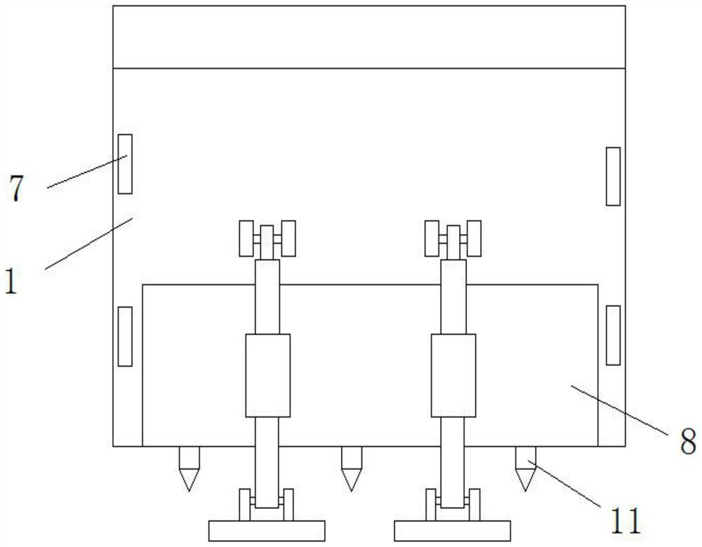
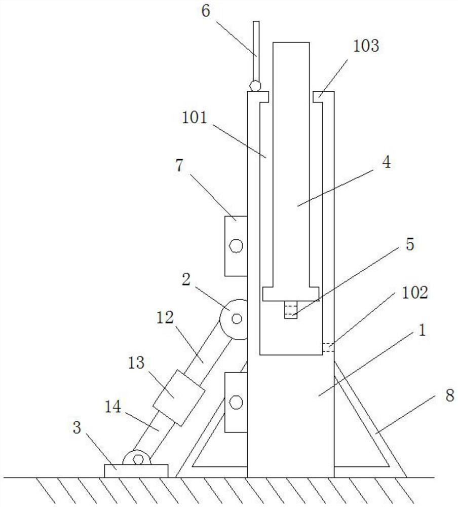
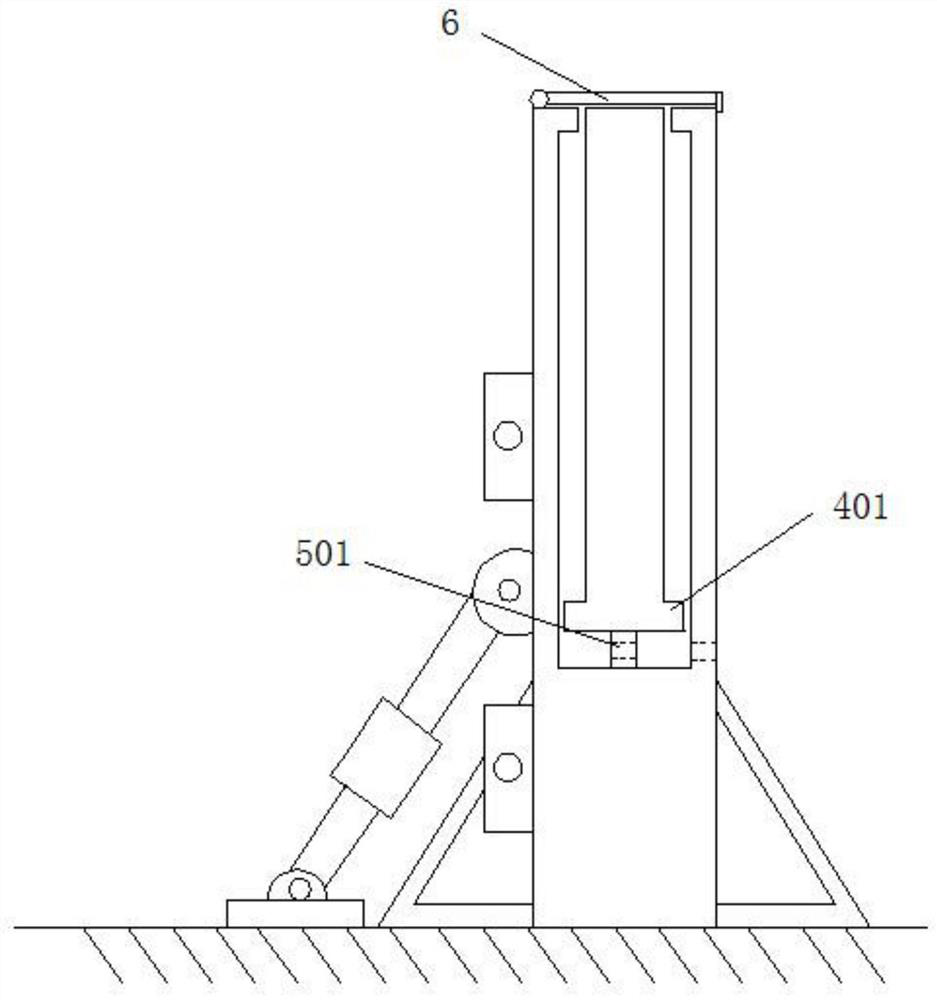
[0022] Such as Figure 1 to Figure 5 As shown, the water-retaining device for water conservancy construction in this embodiment is made by connecting several fixed baffles sequentially, and several fixed baffles are connected end-to-end in sequence to form a water-retaining construction area; the fixed baffles include fixed braces Plate 1, floating baffle 4, the fixed support plate 1 is ...


PUM


Abstract

The invention discloses a water retaining device for hydraulic engineering construction. The water retaining device is made in the mode that multiple fixing baffles are connected in sequence. Each fixing baffle comprises a fixed supporting plate and a suspended baffle. Each fixed supporting plate is in a rectangular plate shape, and an opening groove which transversely penetrates through each fixed supporting plate is formed in the top end of each fixed supporting plate. A protective cover which is used for sealing the top end of the corresponding opening groove is arranged at the top end of each fixed supporting plate. One end of each protective cover is connected with the front side of the top end of the corresponding fixed supporting plate through a hinge, and the other side of each protective cover is connected with the rear side of the top end of the corresponding fixed supporting plate through a buckle. Each suspended baffle is made of wood materials or plastic, the length of each suspended baffle and the length of the corresponding fixed supporting plate are same, and each suspended baffle is arranged in the corresponding opening groove and can longitudinally slide relativeto the corresponding opening groove. A water inlet through hole is formed in the rear end face of each fixed supporting plate and communicates with the corresponding opening groove.

Description

technical field [0001] The invention relates to the field of water conservancy construction, in particular to a water retaining device for water conservancy construction. Background technique [0002] Water retaining device refers to the temporary enclosure structure built for the construction of permanent water conservancy facilities in the construction of water conservancy projects. The water retaining devices in the art are generally formed by connecting and enclosing multiple fixed baffles. The fixed baffles are directly produced and formed by the manufacturer. They occupy a large space and do not use storage and transportation. , It is often necessary to use a crane to hoist engineering equipment into the water-retaining area. Since the height of the fixed baffle is not easy to adjust, the crane will not be able to clearly understand the specific environment of the hoisting position because the height of the fixed baffle is too high during hoisting, resulting in The ho...

Claims


Application Information

Patent Timeline
Patent Type & Authority Applications(China)
IPC IPC(8): E02D19/02E02D19/04
CPCE02D19/02E02D19/04
Inventor 代振明王鹏宰德池张光鹏刘琳刘海燕石泽辉王建成张恒超
Owner 代振明
Why Eureka
Try Eureka