A collision detection method, device, collision detector, system and storage medium
A technology of collision detection and detector, which is applied in the field of electronic appliances and can solve problems such as dead angles in sensor installation positions
- Summary
- Abstract
- Description
- Claims
- Application Information
AI Technical Summary
Problems solved by technology
Method used
Image
Examples
Embodiment 1
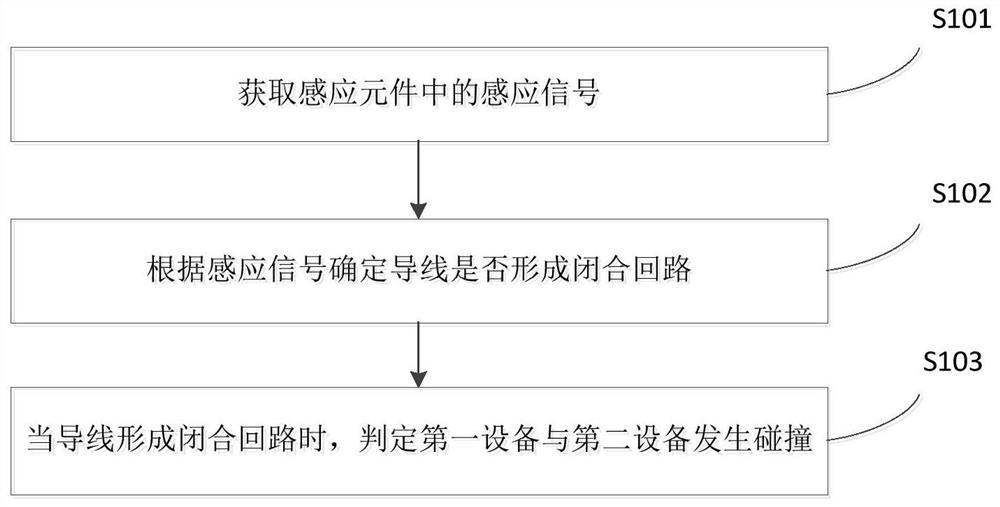
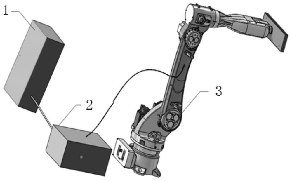
[0038] Embodiment 1 of the present invention provides a collision detection method, which is applied to a collision detection device. The collision detection device is provided with a sensing element, and the sensing element is provided with a sensing area for a wire to pass through, wherein the wire is used to connect the first metal structure of the first device and the second metal of the second device structure. figure 1 It is a schematic flowchart of the collision detection method in Embodiment 1 of the present invention, such as figure 1 As shown, the collision detection method in Embodiment 1 of the present invention includes the following steps:
[0039] S101: Acquire a sensing signal in the sensing element.
[0040] S102: Determine whether the wire forms a closed loop according to the sensing signal.
[0041] As a specific implementation manner, to determine whether the wire forms a closed loop according to the sensing signal, the following technical solutions may ...
Embodiment 2
[0049] Embodiment 2 of the present invention provides a collision detection device. The collision detection device is provided with a sensing element, and the sensing element is provided with a sensing area for a wire to pass through, wherein the wire is used to connect the first metal structure of the first device and the second metal of the second device structure. Figure 4 It is a schematic structural diagram of the collision detection device in Embodiment 2 of the present invention, such as Figure 4 As shown, the collision detection apparatus in Embodiment 2 of the present invention includes an acquisition module 40 , a processing module 42 and a determination module 44 .
[0050] Specifically, the acquiring module 40 is configured to acquire the sensing signal in the sensing element.
[0051] The processing module 42 is configured to determine whether the wire forms a closed loop according to the sensing signal.
[0052] The determining module 44 is configured to det...
Embodiment 3
[0055] An embodiment of the present invention further provides a collision detector, the collision detector includes a sensing element, a sensing area for a wire to pass through is provided in the sensing element, and the sensing element is used to generate a sensing signal; the processor and Memory, where the processor and memory may be connected by a bus or otherwise.
[0056] The processor may be a central processing unit (Central Processing Unit, CPU). The processor may also be other general-purpose processors, digital signal processors (Digital Signal Processor, DSP), application specific integrated circuit (Application Specific Integrated Circuit, ASIC), Field-Programmable Gate Array (Field-Programmable Gate Array, FPGA) or other Chips such as programmable logic devices, discrete gate or transistor logic devices, discrete hardware components, or a combination of the above types of chips.
[0057] As a non-transitory computer-readable storage medium, the memory can be us...
PUM
 Abstract
Description
Claims
Application Information
 - R&D
- Intellectual Property
- Life Sciences
- Materials
- Tech Scout
- Unparalleled Data Quality
- Higher Quality Content
- 60% Fewer Hallucinations
Browse by: Latest US Patents, China's latest patents, Technical Efficacy Thesaurus, Application Domain, Technology Topic, Popular Technical Reports.
© 2025 PatSnap. All rights reserved.Legal|Privacy policy|Modern Slavery Act Transparency Statement|Sitemap|About US| Contact US: help@patsnap.com


