Mistaken-touch-preventing heat-dissipation anti-skid keyboard

An anti-mistouch, anti-slip technology, applied in the direction of instrument, electrical digital data processing, user/computer interaction input/output, etc., can solve the problem of inaccurate finger drop position and easy mistouch

Inactive Publication Date: 2020-09-29
万亚山
View PDF0 Cites 2 Cited by
  • Summary
  • Abstract
  • Description
  • Claims
  • Application Information

AI Technical Summary

Problems solved by technology

[0005] The purpose of the present invention is to provide an anti-mis-touch heat dissipation and non-slip keyboard that can reduce th

Method used


Image

  • Mistaken-touch-preventing heat-dissipation anti-skid keyboard
  • Mistaken-touch-preventing heat-dissipation anti-skid keyboard
  • Mistaken-touch-preventing heat-dissipation anti-skid keyboard

Examples


Embodiment 1

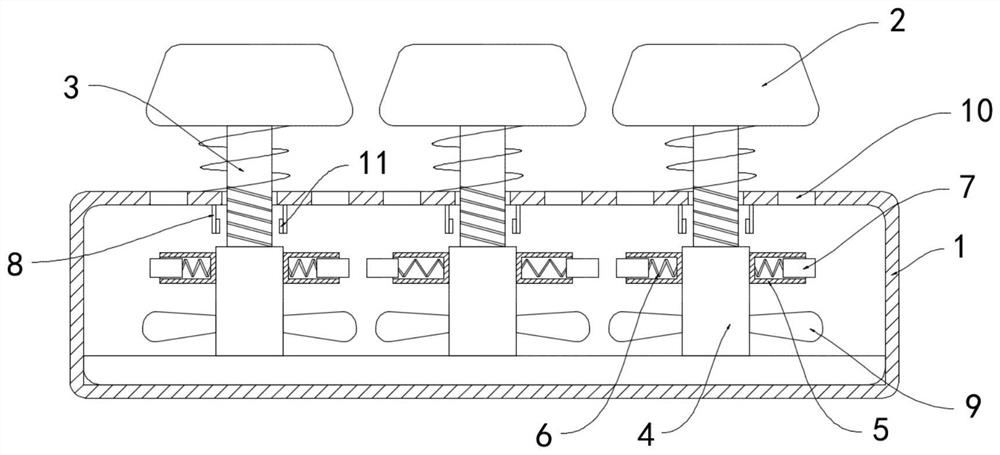
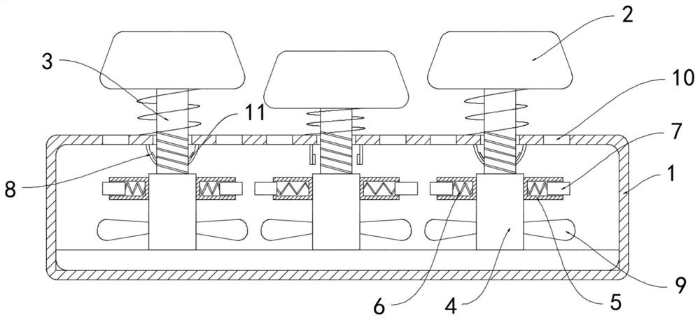
[0018] Such as Figure 1-2 As shown, an anti-mistouch type heat dissipation anti-slip keyboard includes a housing 1 and a plurality of buttons 2 installed above the housing 1, the lower ends of the buttons 2 are fixedly connected with threaded rods 3, and the inner bottom surface of the housing 1 is rotatably connected with The threaded cylinder 4, the lower end of the threaded rod 3 runs through the housing 1 and extends into the threaded cylinder 4, the threaded rod 3 is threadedly matched with the threaded cylinder 4, and the side wall of the threaded cylinder 4 is fixedly connected with a plurality of limit cylinders 5, the limit The cylinder 5 is fixedly connected with the permanent magnet block 7 through the tension spring 6, and the inner top surface of the housing 1 is provided with a plurality of magnetic shrapnel 8 matched with the threaded rod 3, and the magnetic shrapnel 8 and the permanent magnet block 7 repel each other with the same polarity. , the side wall of ...

Embodiment 2

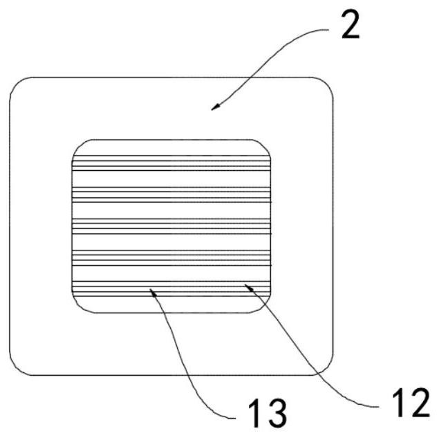
[0022] Such as image 3 As shown, the difference between this embodiment and Embodiment 1 is that the upper surface of the button 2 is provided with a plurality of bar-shaped grooves 12, and the arrangement of the plurality of bar-shaped grooves 12 is relatively dense, which can increase the resistance on the surface of the button 2 , to prevent fingers from slipping, and the diameter of the strip groove 12 is less than 2mm, the sweat on the surface of the button 2 can be sucked into the strip groove 12 through the capillary effect, and the button 2 is embedded with multiple closed coils 13, and the multiple closed coils 13 is extended into the bar-shaped groove 12, and the bar-shaped groove 12 can prevent fingers from directly contacting the closed coil 13 to cause discomfort.

[0023] In this embodiment, when the button 2 is pressed by a finger, the permanent magnet block 7 rotates with the threaded cylinder 4. According to the principle of electromagnetic induction, when th...


PUM


Abstract

The invention belongs to the field of computer accessories, in particular to a mistaken-touch-preventing heat-dissipation anti-skid keyboard. The keyboard comprises a shell and a plurality of keys arranged above the shell, the lower end of the key is fixedly connected with a threaded rod; the inner bottom surface of the shell is rotationally connected with a threaded cylinder; the lower end of thethreaded rod penetrates through the shell and extends into the threaded cylinder; the threaded rod is in threaded fit with the threaded cylinder; a plurality of limiting cylinders are fixedly connected to the side wall of the threaded cylinder; a permanent magnet block is fixedly connected into the limiting cylinder through an extension spring, a plurality of magnetic elastic pieces matched withthe threaded rods are arranged on the inner top face of the shell, the magnetic elastic pieces and the permanent magnet block repel each other in a homopolar mode, and a plurality of fan blades arranged in an annular array mode are fixedly installed outside the threaded cylinder. According to the invention, in the falling process of pressing one of the keys by a finger, frictional resistance is generated to the falling of the adjacent key, the condition of mistaken touch caused by deviation of the falling position of the finger is prevented, sweat on the key can be quickly removed, and the finger is prevented from sliding.

Description

technical field [0001] The invention belongs to the field of computer accessories, and in particular relates to an anti-mistouch type heat dissipation anti-slip keyboard. Background technique [0002] With the rapid development of informatization, most families are equipped with computers, which greatly enrich people's learning and entertainment. Among them, the keyboard is a common computer accessory, which is a kind of instruction and data input device for operating equipment. [0003] When using a computer for office work, it is inevitable to use the keyboard, and the keys on the keyboard are densely arranged. When people tap the keys with their fingers, they often press a key while the finger's position is inaccurate. Under the action of friction, another button is carried down, and a false touch occurs, which leads to an error in the input command, which brings inconvenience to the office, and when the keyboard is used for a long time, the sweat on the fingers will adhe...

Claims


Application Information

Patent Timeline
IPC IPC(8): G06F3/02
CPCG06F3/0202G06F3/0219
Inventor 万亚山房书明马俊玲
Owner 万亚山
Why Eureka
Try Eureka