Beam-rail integrated telescopic device of large-span railway steel bridge and design method thereof

A telescoping device and large-span technology, which is applied in the direction of railway fixing devices, bridge construction, bridges, etc., can solve problems such as the design method of telescopic devices with less beam ends, and achieve the effect of meeting the requirements of vertical support stiffness and reducing longitudinal telescopic resistance

Active Publication Date: 2020-10-02
RAILWAY ENG RES INST CHINA ACADEMY OF RAILWAY SCI +3
View PDF4 Cites 2 Cited by
  • Summary
  • Abstract
  • Description
  • Claims
  • Application Information

AI Technical Summary

Problems solved by technology

And for beam end expansion and contraction, most researchers only pay attention to the product application of beam end expansion device, and there are few design methods for beam end expansion device

Method used


Image

  • Beam-rail integrated telescopic device of large-span railway steel bridge and design method thereof
  • Beam-rail integrated telescopic device of large-span railway steel bridge and design method thereof
  • Beam-rail integrated telescopic device of large-span railway steel bridge and design method thereof

Examples


Embodiment 1

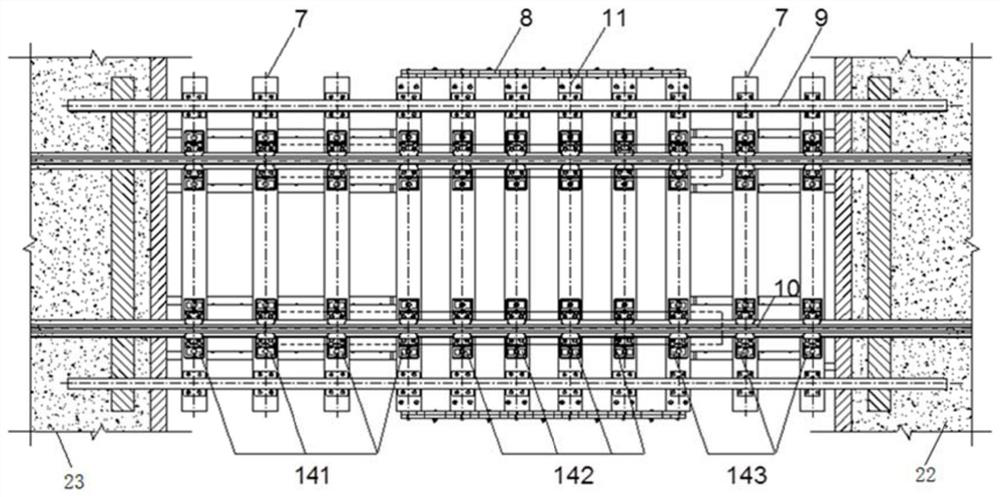
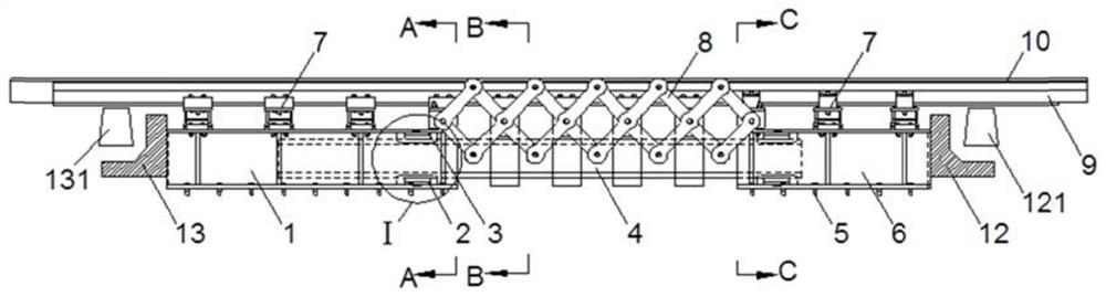
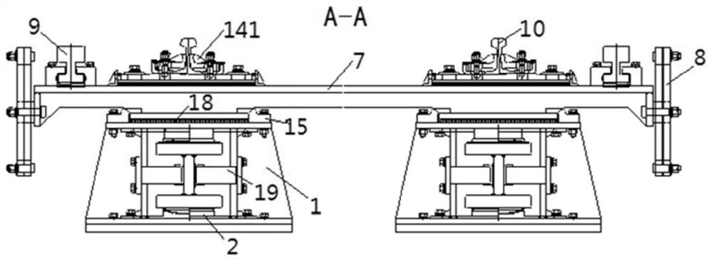
[0047]A beam-rail integrated telescopic device for a long-span railway steel bridge, comprising a movable end displacement box 1, a fixed end displacement box 6, a supporting beam 4, a fixed steel sleeper 7, a movable steel sleeper 11, a connecting rod system 8 and a lateral rail9.

[0048] The movable end displacement box 1 is fixedly connected with the 23 ends of the approach bridge, and the fixed end displacement box 6 is fixedly connected with the main bridge 22 ends. The connection between the displacement box 6 and the pre-embedded steel plate on the side deck of the main bridge is realized by anchor bolts 5 . The movable end displacement box 1, the support beam 4 and the fixed end displacement box 6 are sequentially connected along the longitudinal direction of the railway steel bridge and jointly constitute the lower support structure of the beam-rail integrated telescopic device. 6. One end is longitudinally fixed, and one end of the movable end displacement box 1 is...

Embodiment 2

[0071] The invention provides a performance-based design method of a beam-rail integrated expansion device for a large-span railway steel bridge. The concept of beam-rail integration is used to design the telescopic device at the beam end.

[0072] Its specific technical process is as follows: Figure 5 as shown, Figure 5 The basic process of the performance-based design method of beam-rail integrated telescopic device is given in , including:

[0073] (1) Analyze the rationality of the existing bridge constraint system, and qualitatively propose a reasonable constraint system for the new bridge. By carrying out the beam end displacement analysis, the spatial displacement characteristics of the bridge beam end under different load conditions can be clarified. Specifically, the finite element model of the long-span railway steel bridge can be established, and the beam end can be analyzed under different load conditions. Displacement characteristics of end space; combined wi...


PUM


Abstract

The invention relates to a beam-rail integrated telescopic device of a large-span railway steel bridge and a design method of the beam-rail integrated telescopic device, and belongs to the technical field of railway bridge telescopic devices. The beam-rail integrated telescopic device comprises a movable end displacement box, a fixed end displacement box, a supporting beam, fixed steel sleepers, movable steel sleepers and a connecting rod system. A stock rail of a steel rail telescopic adjuster is connected with the fixed steel sleepers above the movable end displacement box, the fixed steel sleepers above the fixed end displacement box, the movable steel sleepers and concrete sleepers on a main bridge and an approach bridge through different fasteners. The telescopic device can meet the requirement for vertical supporting rigidity, the longitudinal telescopic resistance of the beam end telescopic device can be obviously reduced, and the common splayed defect of the movable steel sleeper is avoided. The invention further provides a design method of the beam-rail integrated telescopic device based on the performance, and the problems that in the prior art, a beam end telescopic device and a steel rail telescopic adjuster are specially and independently designed through a bridge and a rail, and consequently connector fastener design is unreasonable are solved.

Description

technical field [0001] The invention relates to a beam-rail integrated expansion device for a large-span railway steel bridge and a design method thereof, belonging to the technical field of railway bridge expansion devices. Background technique [0002] The long-term operation practice of many high-speed railway long-span steel bridges shows that the expansion device at the beam end is a part of the bridge with many diseases, and it needs to be optimized on the basis of existing products. Sorting out the main defects, analyzing the causes of the defects, and further feedback design are the directions for the optimal design of the telescopic devices at the ends of long-span railway steel bridges. [0003] In addition, long-span railway steel bridges are often equipped with rail telescopic regulators and beam end telescopic devices at the beam end, the main purpose of which is to coordinate the longitudinal expansion and contraction of the upper rails of the bridge and the ma...

Claims


Application Information

Patent Timeline
Patent Type & Authority Applications(China)
IPC IPC(8): E01D19/06E01D19/12E01B11/42
CPCE01D19/06E01D19/12E01B11/42E01B2201/04E01B2202/025
Inventor 韩自力刘晓光江成郭辉蒋金洲胡所亭赵欣欣臧晓秋魏峰高芒芒陈良江赵会东苏朋飞朱颖周勇政赵体波苏永华梁晨徐玉坡杨静静王丽肖鑫严乃杰李彬洋
Owner RAILWAY ENG RES INST CHINA ACADEMY OF RAILWAY SCI
Why Eureka
Try Eureka