Spiral locking device

A locking device and screw technology, which is applied to coupling devices, parts of connecting devices, devices for connecting/disconnecting connecting parts, etc., can solve the problems of long time, complicated installation of screw fastening structures, etc., and save installation costs. , Solve the effect of complex installation

Pending Publication Date: 2020-10-02
JIANGSU ENMAN ELECTRONICS IND CO LTD
View PDF0 Cites 2 Cited by
  • Summary
  • Abstract
  • Description
  • Claims
  • Application Information

AI Technical Summary

Problems solved by technology

[0003] In order to overcome the above-mentioned shortcomings, the object of the present invention is to provide a screw locking device suitable for electric plug connectors and electric plug connector sockets, which realizes quick disassembly and assembly of cable connections and solves the problem of screw fastening structures. The problem of complicated installation and long time consumption greatly saves the installation cost

Method used


Image

  • Spiral locking device
  • Spiral locking device
  • Spiral locking device

Examples


Embodiment

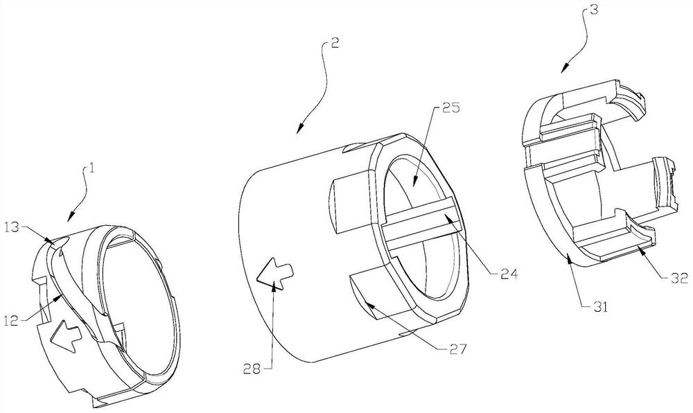
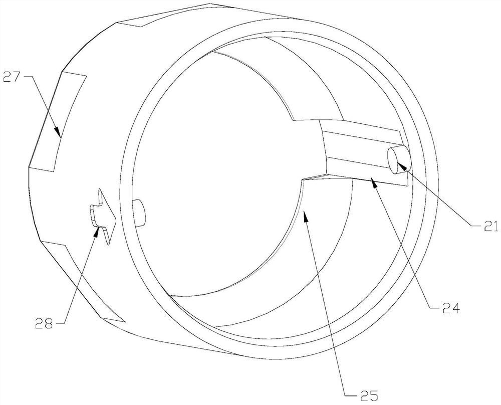
[0035] See attached figure 1 As shown, a screw locking device of the present invention includes a screw body 1 , a screw fixing cap 2 , and a wire harness mechanism 3 . The screw body 1 is fixedly arranged on the electric plug connector 4 or the electric plug connector female base 5 , and a snap-fit ​​groove is arranged on it. The screw fixing cap 2 is detachably connected with the harness mechanism 3 and can be rotatably plugged into the screw body 1 . The screw fixing cap 2 is also provided with a locking portion 21 that can be locked into the locking groove.

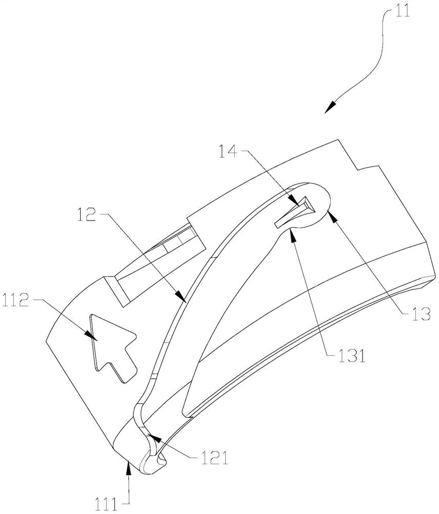
[0036] In this example, see the attached Figure 1-2 As shown, the spiral body 1 is composed of a pair of arc-shaped plates 11 arranged symmetrically and encircled to form a ring structure. One end of the arc-shaped plate 11 is welded and fixed on the electrical plug connector 4 or the electrical plug connector female base 5 , and the other end is used for the screw fixing cap 2 to rotate the plug.

[0037] There ...


PUM


Abstract

The invention discloses a spiral locking device, which comprises a spiral body and a spiral fixing cap, wherein the spiral body is fixedly arranged on an electric plug connector or an electric plug connector female seat, a buckling groove is formed in the spiral body, the spiral fixing cap can be inserted into the spiral body in a rotating mode and is provided with a lock catch part capable of being locked into the buckling groove, the buckling groove comprises a strip-shaped groove body obliquely arranged along the side wall of the spiral body, a groove body opening formed along the edge of the spiral body is formed in one end of the strip-shaped groove body, and a locking structure used for locking the lock catch part is arranged at the other end of the strip-shaped groove body. According to the spiral locking device, rapid disassembly and assembly of cable connection are achieved, the problems that a threaded fastening structure is complex in installation and long in consumed time are solved, and the installation cost is greatly saved.

Description

technical field [0001] The invention relates to the technical field of cable connection equipment, in particular to a screw locking device suitable for an electric plug connector and a female seat of the electric plug connector. Background technique [0002] The electric plug connection is the interaction between the two parts of the electric plug connector and the electric plug connector female seat to achieve the connection effect. It can be used to connect the cable to an electrical or electronic device, or it can be used as two cables. connection between each other. When the cable is connected to the electric plug connector or the female seat of the electric plug connector, an external threaded connection part is usually provided on the electric plug connector or the female seat of the electric plug connector, and then the fixed cable The clamping device is screw-locked on the external thread connection part. However, the existing connection structure is relatively com...

Claims


Application Information

Patent Timeline
IPC IPC(8): H01R4/30H01R13/639H01R13/622H01R13/623
CPCH01R4/307H01R4/30H01R13/639H01R13/622H01R13/623H01R13/625H01R13/641H01R13/5812
Inventor 王传宝
Owner JIANGSU ENMAN ELECTRONICS IND CO LTD
Why Eureka
Try Eureka