Heat dissipation device

A technology of heat dissipation device and support frame, which is applied in the cooling/ventilation of substation/switchgear, details of substation/switch arrangement, electrical components, etc., and can solve the problems of poor cooling effect of cooling fans and other issues

Active Publication Date: 2020-10-02
HUIZHOU POWER SUPPLY BUREAU OF GUANGDONG POWER GRID CO LTD
View PDF17 Cites 2 Cited by
  • Summary
  • Abstract
  • Description
  • Claims
  • Application Information

AI Technical Summary

Problems solved by technology

[0004] The purpose of the present invention is to provide a heat dissipation device to solve the problem of poor ventilation and heat dissipation effect of cooling the power distribution cabinet by using a cooling fan, so as to realize rapid and efficient cooling and ventilation of the surrounding environment of the power distribution cabinet.

Method used


Image

  • Heat dissipation device

Examples


Embodiment 1

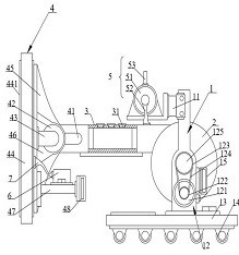
[0048] This embodiment provides a cooling device, such as figure 1 As shown, it includes a support frame 1 , a winding part 2 , a pipe body 3 , a first air extraction assembly 4 and a second air extraction assembly 5 . Wherein, the winding part 2 is rotatably arranged on the support frame 1; one end of the pipe body 3 is wound around the winding part 2, and the other end is a free end; the first air extraction assembly 4 is connected to the free end of the pipe body 3 for The gas around the power distribution cabinet is sucked into the pipe body 3; the second air extraction assembly 5 is arranged on the support frame 1, located on one side of the pipe body 3, can be connected to the pipe body 3, and is located downstream of the gas flow direction, for Vent gas to ambient. In this embodiment, the pipe body 3 is preferably a rubber hose, which is convenient for installation and has a good sealing effect.

[0049] The hot air inside and around the power distribution cabinet pas...

Embodiment 2

[0060] Parts in this embodiment that are the same as or corresponding to those in the first embodiment use the reference numerals that correspond to those in the first embodiment. For simplicity, only the differences between Embodiment 2 and Embodiment 1 are described. The difference is that the heat dissipation device also includes a driving mechanism, which is arranged on the support frame 1 and is used to drive the winding part 2 to rotate to retract the free end of the tube body 3 . The drive mechanism is provided to automatically retract and unwind the free end of the tube body 3, saving time and effort.

[0061] Specifically, the driving mechanism includes a motor 121, a driving gear 122, a driven gear 123 and a chain 124. The motor 121 is arranged on the support frame 1; the driving gear 122 is connected to the output end of the motor 121; On the support frame 1 , the driven gear 123 is sleeved on the rotating shaft 125 ; the chain 124 is wound around the driving gear ...


PUM


Abstract

The invention discloses a heat dissipation device, and belongs to the technical field of electromechanical equipment. The heat dissipation device comprises a support frame, a winding part, a pipe body, a first air exhaust assembly and a second air exhaust assembly, wherein the winding part is rotatably arranged on the support frame, one end of the pipe body is wound on the winding part, the otherend of the pipe body is a free end, the first air exhaust assembly is connected to the free end of the pipe body and is used for sucking air around a power distribution cabinet into the pipe body, andthe second air exhaust assembly is arranged on the support frame, located on one side of the pipe body, capable of being connected into the pipe body, located on the downstream of the air flow direction and used for exhausting air to the external environment. According to the invention, hot air around a power distribution cabinet is exhausted through two air exhaust assemblies in sequence througha pipe body and guided to the far position, so that air circulation around the power distribution cabinet is accelerated, the surrounding environment of the power distribution cabinet is cooled, andthe ventilation and heat dissipation effects are good; and the pipe body is wound around the winding part, the free end of the pipe body is convenient to fold and unfold, and the free end of the pipebody moves flexibly, so that the air sucking position is convenient to adjust, and use is convenient.

Description

technical field [0001] The invention relates to the technical field of electromechanical equipment, in particular to a heat dissipation device. Background technique [0002] Power distribution equipment, especially power distribution cabinets, will generate a lot of heat during operation, resulting in excessively high temperature around the equipment. If the temperature is not cooled in time, the normal operation and service life of the equipment will be affected. [0003] Usually, the cooling measure adopted is to install a cooling fan inside and outside the power distribution cabinet, but the cooling fan cannot efficiently exchange the air in the cabinet with the surrounding air, and the effect of air circulation is not good. When the temperature near the power distribution cabinet is high, And when using the heat dissipation fan to carry out the exhaust operation, the heat dissipation fan will draw in more hot air, causing the temperature in the power distribution cabinet...

Claims


Application Information

Patent Timeline
Patent Type & Authority Applications(China)
IPC IPC(8): H02B1/56
CPCH02B1/565
Inventor 李国良黄日光陈文其关国亮李宗翰谭世钊吴贻标
Owner HUIZHOU POWER SUPPLY BUREAU OF GUANGDONG POWER GRID CO LTD
Why Eureka
Try Eureka