Device for supporting mobile equipment terminal through front rotating structure
A technology of mobile equipment and rotating structure, applied in the direction of mechanical equipment, telephone structure, supporting machine, etc., can solve the problems of poor stability, lack of functions and emotional modeling of mobile equipment brackets, etc., achieve stable use, meet individual needs, Simple operation effect
- Summary
- Abstract
- Description
- Claims
- Application Information
AI Technical Summary
Problems solved by technology
Method used
Image

Examples
Embodiment 1
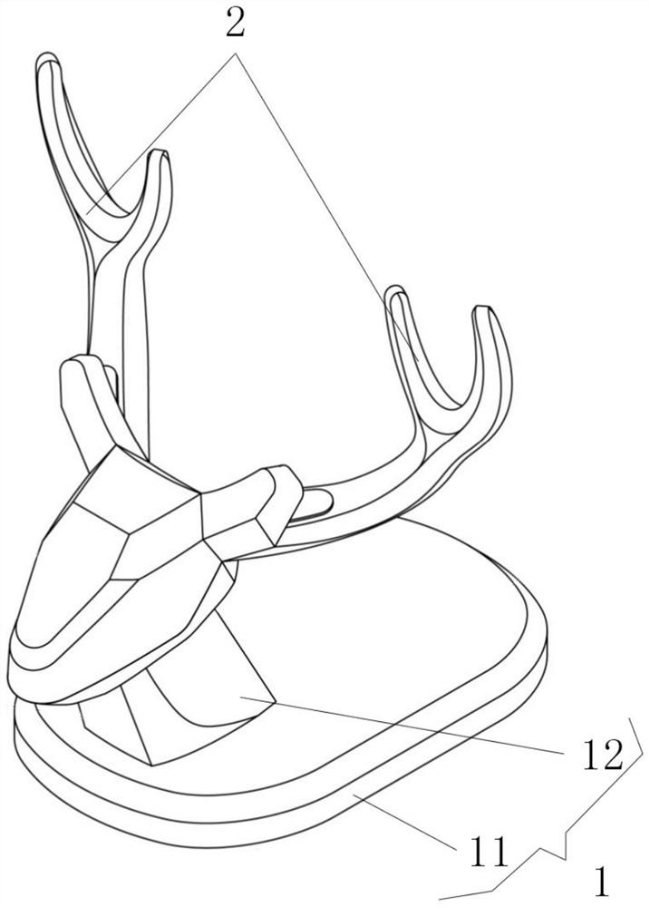
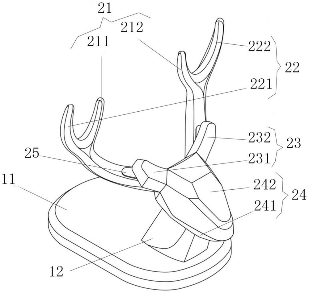
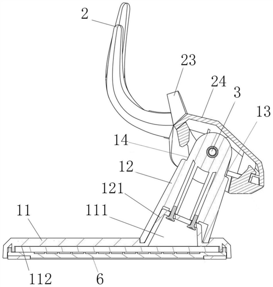
[0034] see Figure 1-9 , the present invention provides a technical solution: a device for supporting a mobile device terminal with a front rotating structure, including a base part 1 and a support mechanism 2; the base part 1 is movably connected with the support mechanism The movable node part formed by the connection position between the mechanisms 2 is located at the front end of the support mechanism 2, and the movable node part is used to move the center of gravity of the mobile equipment bracket formed by the support mechanism 2 forward until it is close to the front edge of the base part 1; the movable node part is used for To change the angle of inclination of the support mechanism 2 to adjust the angle of use when the mobile device bracket supports the mobile device; the support mechanism 2 is used to support the mobile device to realize the horizontal and vertical use of the mobile device. A recessed data line routing space 9 is formed between the seat parts 1 for t...
Embodiment 2
[0044] exist Figure 10 , shows other combined applications of the base member 1 and the support mechanism 2, the support mechanism 2 passes through the connecting member 3 and the top end of the abutment 12; in this exemplary embodiment, the cross-sectional shape of the support mechanism 2 is inverted "L "shaped structure, and the top of the straight section of the supporting mechanism 2 is provided with a blocking part, that is, the blocking part assists the supporting arm; when in use, the supporting mechanism 2 supports the mobile device, and at this time, under the action of the connecting piece 3, the supporting mechanism 2 can Change the inclination angle of itself to adjust the use angle and viewing angle of the mobile device. At this time, the rotation of the support mechanism 2 is directly realized through the connecting piece 3 to change the inclination angle of the support mechanism 2; wherein, the Related structures such as the stabilization mechanism 6 , the scre...
Embodiment 3
[0046] exist Figure 11 In , other combined applications of the base member 1 and the support mechanism 2 are shown. The overall cross-sectional shape of the support mechanism 2 is a "U"-shaped structure, and the support mechanism 2 is movably connected with the abutment 12 through the connecting piece 3; in this exemplary implementation In the example, the rotating part 24 of the support mechanism 2 and the supporting part form an integrated structure, so that when changing the use angle of the mobile device, the use angle of the mobile device can be changed by directly rotating the support mechanism; among them, the first embodiment The stability-enhancing mechanism 6, the screw structure 32, the limiting mechanism, the snap-fit structure and other related structures involved in the present embodiment 3 are all applicable to the third embodiment, so details are not repeated here.
PUM
 Abstract
Description
Claims
Application Information
 - Generate Ideas
- Intellectual Property
- Life Sciences
- Materials
- Tech Scout
- Unparalleled Data Quality
- Higher Quality Content
- 60% Fewer Hallucinations
Browse by: Latest US Patents, China's latest patents, Technical Efficacy Thesaurus, Application Domain, Technology Topic, Popular Technical Reports.
© 2025 PatSnap. All rights reserved.Legal|Privacy policy|Modern Slavery Act Transparency Statement|Sitemap|About US| Contact US: help@patsnap.com