Three-position positioning interlocking mechanism traction lock plate anti-misoperation reinforcement mechanism assembly and drawer unit
A positioning interlocking and anti-misoperation technology, which is applied to switchgear, electrical components, pull-out switch cabinets, etc., can solve the problems of insufficient fast and convenient operation, increased operating resistance, and difficult manual operation, etc. Normal, convenient, no abnormality, reliable positioning, and simplified operation
- Summary
- Abstract
- Description
- Claims
- Application Information
AI Technical Summary
Problems solved by technology
Method used
Image
Examples
Embodiment 1
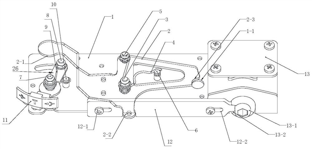
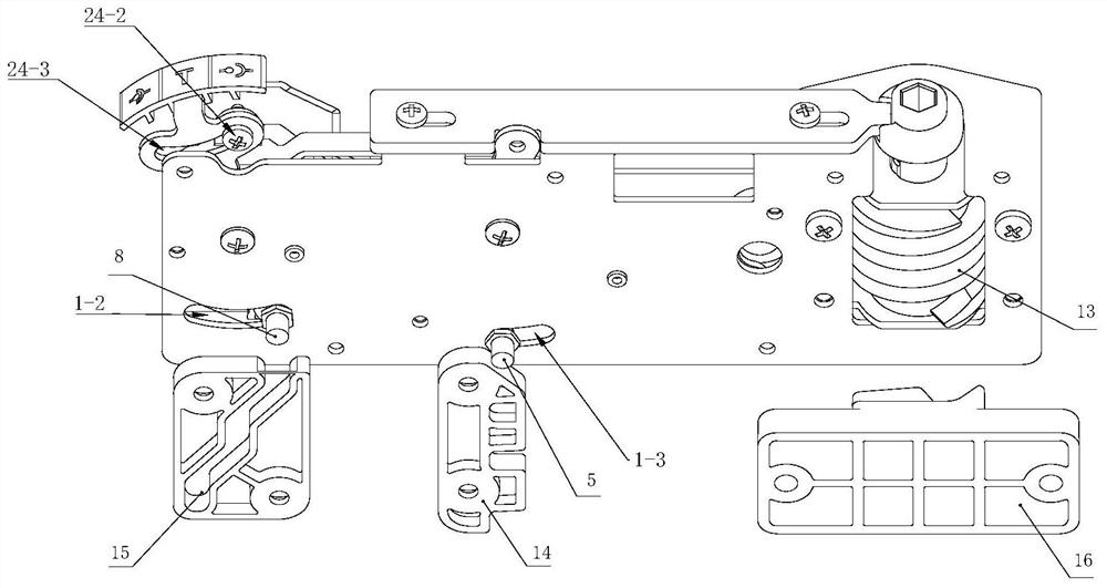
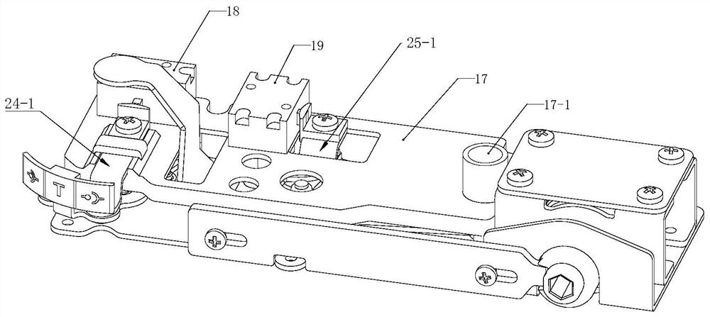
[0062] Embodiment 1: as figure 1 As shown in ~9C, a three-position positioning interlocking mechanism traction lock plate anti-misoperation boosting mechanism can realize the functions of three-position positioning display, switch closing lock, and propulsion mechanism locking.
[0063] The three-position positioning interlocking mechanism traction lock plate anti-misoperation boosting mechanism includes a position positioning interlocking mechanism, a position indicating mechanism and a boosting boosting mechanism, the boosting boosting mechanism is a spiral boosting boosting mechanism, and the position positioning interlocking mechanism is used The drawer 22 is positioned and unlocked in cooperation with the position locating piece 14 on the unit room shelf, and the screw booster mechanism is used to cooperate with the groove-shaped locating piece 16 on the unit room shelf to perform the rocking operation of the drawer 22. A traction locking plate 12 is set between the posit...
Embodiment 2
[0095] Embodiment 2: On the basis of Embodiment 1, the traction lock plate 12 and the screw power boosting mechanism are cancelled, and the interlocking mechanism of Embodiment 2 can satisfy the application functions of the drawer 22 in three-position pushing and pulling out by hand Standard technical requirements. However, it is only used in drawers 22 with current levels of 125A, 250A, and 63A. In these drawers 22 with current levels, the plug pressure of the main and auxiliary circuit plugs is not greater than 900N, which is relatively in line with manual operation requirements.
[0096] However, there are many types of drawer unit structures and current ratings. Only the hand-pull and hand-pull operation methods of this embodiment 2 cannot meet the push operation of the drawer 22 with a high current level. It is necessary to add a screw booster mechanism and a traction lock plate. The three-position positioning interlock mechanism traction lock plate anti-misoperation powe...
Embodiment 3
[0098] Chinese patent application document CN110890711A discloses a removable three-position operating functional unit, which discloses a lever-increasing propulsion mechanism, which includes a lever-increasing upward propulsion mechanism 27 and the push mechanism 28 under the lever boost, the operating tool 29 of the lever operation port of the push mechanism 27 and the lever boost lower push mechanism 28 inserted into the lever boost carries out the push operation of the drawer 22.
[0099] This embodiment 3 is obtained on the basis of the structural principle of embodiment 1 in combination with the lever-increased upper propulsion mechanism and the lever-intensified lower propulsion mechanism disclosed in the Chinese patent application document CN110890711A. The upper operating port formed by the rotating shaft assembly is the lever-enhancing upward propulsion mechanism, and the lower operating port formed by the double-column rotating shaft assembly is the lever-enhancing l...
PUM
 Abstract
Description
Claims
Application Information
 - R&D
- Intellectual Property
- Life Sciences
- Materials
- Tech Scout
- Unparalleled Data Quality
- Higher Quality Content
- 60% Fewer Hallucinations
Browse by: Latest US Patents, China's latest patents, Technical Efficacy Thesaurus, Application Domain, Technology Topic, Popular Technical Reports.
© 2025 PatSnap. All rights reserved.Legal|Privacy policy|Modern Slavery Act Transparency Statement|Sitemap|About US| Contact US: help@patsnap.com


