Method for non-intrusively determining the temperature of a fluid flowing through a conduit portion

A fluid and section technology, which is applied in the temperature measurement of moving fluid, the application of thermometers with direct heat-sensitive electric/magnetic elements, and the application of thermometers, can solve the problems of not considering the thermal conductivity of the fluid boundary layer, etc.

Active Publication Date: 2020-10-20
ABB (SCHWEIZ) AG
View PDF9 Cites 0 Cited by
  • Summary
  • Abstract
  • Description
  • Claims
  • Application Information

AI Technical Summary

Problems solved by technology

The described method however has the serious disadvantage that it does not ta

Method used


Image

  • Method for non-intrusively determining the temperature of a fluid flowing through a conduit portion
  • Method for non-intrusively determining the temperature of a fluid flowing through a conduit portion
  • Method for non-intrusively determining the temperature of a fluid flowing through a conduit portion

Examples


Embodiment Construction

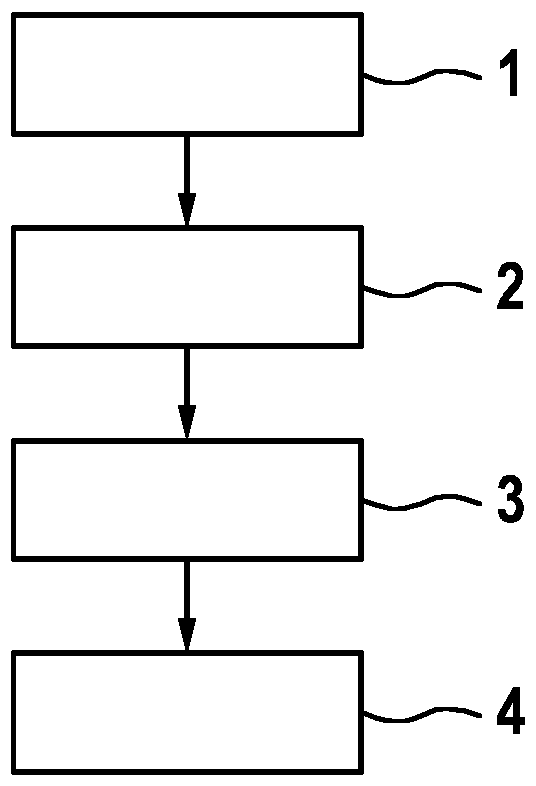
[0065] figure 1 is shown for measuring the flow through the figure 2 The temperature T of the fluid 12 of the conduit section 11 shown in M steps of the method. In a first step 1, the temperature T of the conduit section 11 is determined wa . In a second step 2, a reference temperature T is detected at a distance from the surface 14 of the conduit section 11 e . In a third step 3 , the heat transfer properties, in particular the thermal resistance, of the boundary layer 15 of the fluid 12 at the inner wall 16 of the conduit section 11 are determined as a function of at least one value of a state variable and at least one material property of the fluid 12 .

[0066] In a fourth step 4, depending on the heat transfer properties of the boundary layer 15, the heat transfer properties of the conduit section 11, in particular the thermal resistance, the temperature T of the conduit section wa and reference temperature T e Measure the temperature T of the fluid 12 M . Refe...


PUM


Abstract

The invention relates to a method for determining the temperature of a fluid (12) flowing through a conduit portion (11), wherein: - the temperature of the conduit portion (11) is ascertained; a reference temperature at a distance (13) from a surface (14) of the conduit portion (11) is detected; - the heat-transfer behaviour, in particular the thermal resistance, of a boundary layer (15) of the fluid (12) at an inner wall (16) of the conduit portion (11) is determined on the basis of at least one material property and at least one value of a state variable of the fluid (12); and - the temperature of the fluid (12) is determined on the basis of the heat-transfer behaviour of the boundary layer (15), the heat-transfer behaviour, in particular the thermal resistance, of the conduit portion (11), the temperature of the conduit portion (11), and the reference temperature.

Description

technical field [0001] The invention relates to a method for determining the temperature of a fluid flowing through a conduit section. Fluids are at least but not exclusively understood to mean liquids, gases and bulk materials. Background technique [0002] One such method is known, for example, from WO 2017 / 131546 A1. The method described therein is characterized in that a handle is arranged between the point at which the ambient temperature is measured and the point at which the surface temperature of the outer surface of the conduit section is measured, from which the thermal resistance is known. With the aid of the known thermal resistance and the two measured temperatures, according to the disclosure, the heat flow through the handle should be calculated and from this heat flow the temperature of the fluid should be calculated. The described method however has the serious disadvantage that the final heat-conducting capacity of the fluid boundary layer is not taken in...

Claims


Application Information

Patent Timeline
IPC IPC(8): G01K13/02G01K7/42
CPCG01K7/427G01K13/02G01K13/024G01F1/6884
Inventor J·格布哈特G·佐萨莱A·德克W·达克J·霍斯特科特P·乌德P·萨斯U·阿伦德
Owner ABB (SCHWEIZ) AG
Why Eureka
Try Eureka