Supercharge Your Innovation With Domain-Expert AI Agents!

A cable trench bridge structure

A bridge structure and cable trench technology, which is applied in the field of electric power engineering, can solve problems such as entangled cables and the inability to ensure the orderliness of cables

Active Publication Date: 2021-08-24
福建宏瑞建设工程有限公司
View PDF17 Cites 0 Cited by
  • Summary
  • Abstract
  • Description
  • Claims
  • Application Information

AI Technical Summary

Problems solved by technology

[0004] Because cables are sometimes added in the process of electric power construction, but when adding cables in the above-mentioned related technologies, the crimping mechanism needs to be removed, and at this time there is no guarantee that the cables can be kept neat, especially some cables with smaller diameters are more likely to be entangled together

Method used


Image

  • A cable trench bridge structure
  • A cable trench bridge structure
  • A cable trench bridge structure

Examples


Embodiment 1

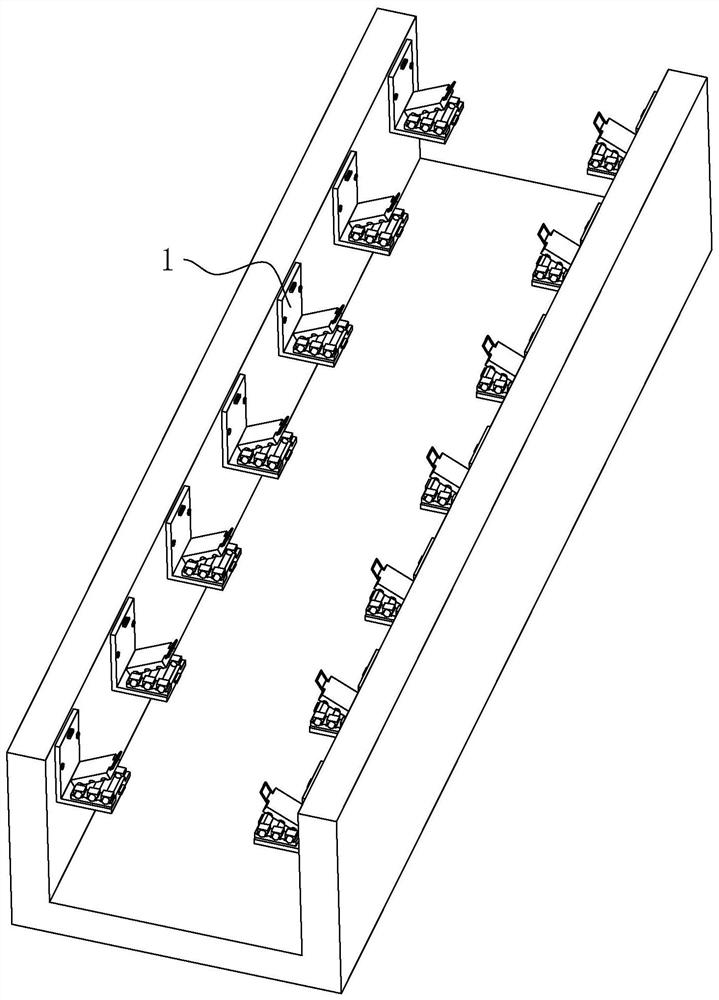
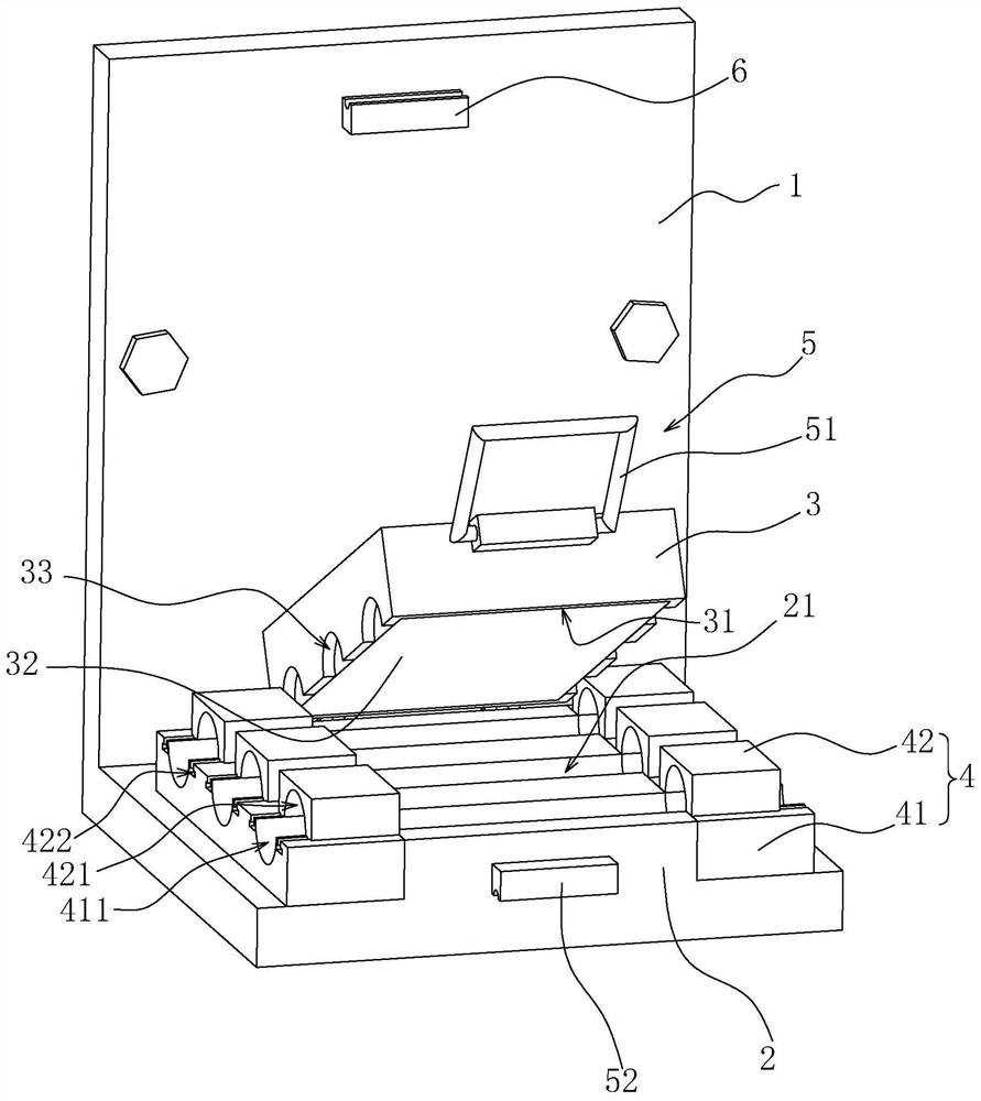
[0040] refer to figure 1 and figure 2 , the bridge structure includes a bridge body 1 arranged on the side wall of the cable ditch, the bridge body 1 is provided with a placement platen 2, and the placement platen 2 is provided with a number of installation grooves 21 consistent with the length direction of the cable trench, and above the placement platen 2 There is also hingedly provided with a pressing seat 3 which cooperates with the placing platen 2 to press the cable.

[0041] refer to figure 2 , a side surface of the pressing seat 3 facing the placing platen 2 is provided with an embedded groove 31, and a flexible pad 32 is arranged in the embedded groove 31. The flexible pad 32 can be rubber, sponge, flexible plastic, etc. with reset ability. The flexible pad 32 is made of elastic material, and the thickness of the flexible pad 32 is equal to the groove depth of the embedded groove 31. After the flexible pad 32 is installed in the embedded groove 31, the end of the ...

Embodiment 2

[0050] refer to Figure 4 and Figure 5 The difference between Embodiment 2 and Embodiment 1 is that the locking mechanism 5 is different. In Embodiment 2, the locking mechanism 5 includes a clamping joint 53 arranged at one end of the positioning splint 42, and a clamping joint is provided on the pressing seat 3 53 is inserted into the clamping slot 54, when the clamping joint 53 is inserted into the clamping slot 54, the pressing seat 3 and the placing platen 2 are in a close state. The engaging grooves 54 increase sequentially from the direction of the hinge point of the pressing base 3 to the direction away from the hinge point.

[0051] refer to Figure 5 and Image 6 At the same time, the bottom position in the snap groove 54 is also provided with a positioning protrusion 541, and the bottom of the snap joint 53 is provided with a positioning groove 531 for the positioning protrusion 541 to be inserted into. The aperture of the positioning groove 531 is also larger th...


PUM


Abstract

The application discloses a cable trench bridge structure, which relates to the technical field of electric power engineering, and improves the problem that the original cables are easily entangled when adding cables. It includes a bridge body arranged on the side wall of the cable trench, and the bridge The body includes a placing platform for placing cables, and the placing platform is provided with a number of installation grooves consistent with the length direction of the cable groove, and the two sides of the placing platform are provided with clamping devices for clamping cables. The tightening device includes a positioning splint and a positioning base plate that are docked up and down. The positioning base plate is provided with a lower positioning groove corresponding to the installation groove and for the cable to be laid. There are multiple positioning splints, and each of the positioning splints The bottoms are provided with upper positioning grooves corresponding to the lower positioning grooves. The application can avoid cables from being tangled together when cables are added.

Description

technical field [0001] The present application relates to the technical field of electric power engineering, and in particular, to a cable trench bridge structure. Background technique [0002] With the rapid development of people's living standards, the power distribution equipment in power engineering will also increase. In the construction of power engineering, the laying of cables is a very important part, and the cable trench is the trench for laying cables. [0003] A bridge will be set up in the cable trench to facilitate the laying of cables, so that the multi-strand cables can be arranged neatly and at the same time improve the stability of the cable setting. For example, the Chinese utility model patent with the authorization announcement number CN210430792U proposes a bridge for easy cable fixing, which includes a U-shaped tray, a top cover, bolts, a line dividing baffle, a tray mounting plate and a wire pressing mechanism. Both ends of the bottom surface of the ...

Claims


Application Information

Patent Timeline
Patent Type & Authority Patents(China)
IPC IPC(8): H02G9/02H02G9/06H02G3/04
CPCH02G3/0406H02G3/045H02G9/02H02G9/06
Inventor 郑志远陈奕群魏建明黄青山
Owner 福建宏瑞建设工程有限公司
Features
  • R&D
  • Intellectual Property
  • Life Sciences
  • Materials
  • Tech Scout
  • Unparalleled Data Quality
  • Higher Quality Content
  • 60% Fewer Hallucinations
Learn More