
LED illuminating lamp device with adjustable illumination angle

A technology of LED lighting and illumination angle, applied in lighting devices, lighting devices, lighting auxiliary devices, etc., can solve the problems of narrow light source adjustment range and inconvenient use.

Inactive Publication Date: 2020-10-27
王学恒
View PDF0 Cites 1 Cited by
  • Summary
  • Abstract
  • Description
  • Claims
  • Application Information

AI Technical Summary

Problems solved by technology

[0004] Based on the technical problems that the existing LED lamps have a narrow adjustment range of the light source and are inconvenient to use when working outdoors, the present invention proposes an LED lighting device with an adjustable irradiation angle

Method used


Image

  • LED illuminating lamp device with adjustable illumination angle
  • LED illuminating lamp device with adjustable illumination angle
  • LED illuminating lamp device with adjustable illumination angle

Examples


Embodiment 1

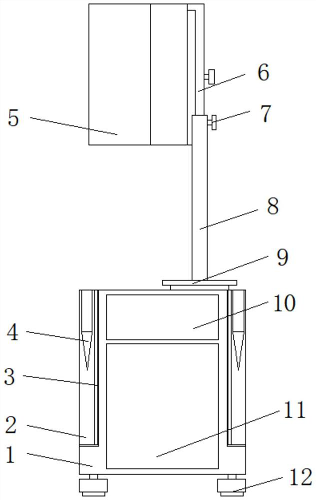
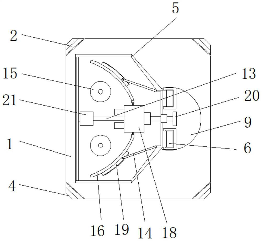
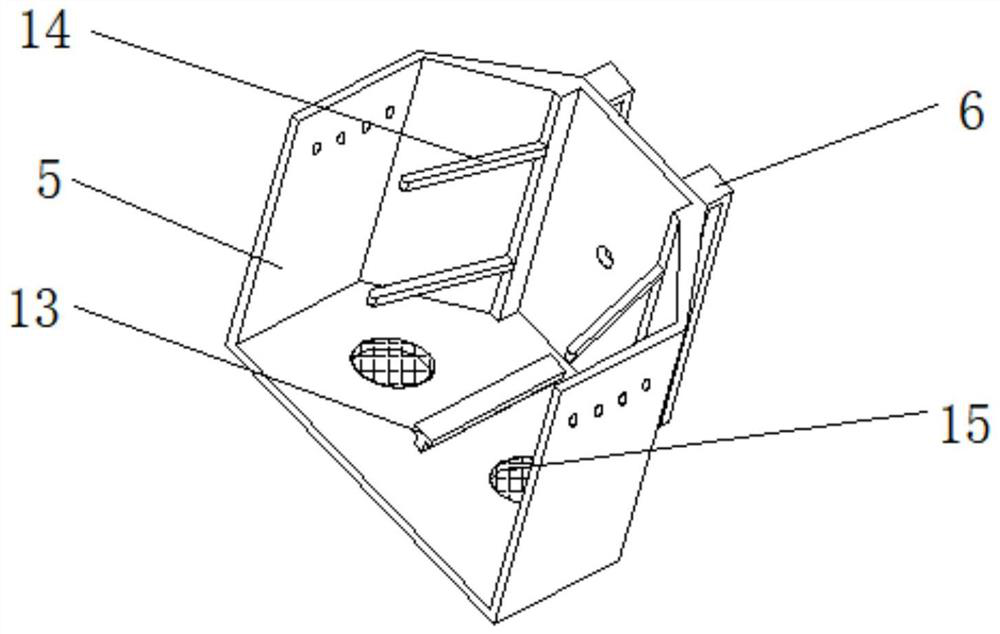
[0027] refer to Figure 1-4 , an LED lighting device with adjustable irradiation angle, including a housing 1, universal wheels 12 with foot brakes are fixedly installed at the four corners of the bottom of the housing 1, and the side of the housing 1 is plugged with a hasp lock. The battery pack 11, the top of the housing 1 is fixedly equipped with an electric rotating table 9, and the top of the electric rotating table 9 is fixedly installed with two supporting mechanisms, and the lampshade 5 is fixedly installed between the sides of the two supporting mechanisms, and the housing 1 The side of the lampshade 5 is screwed with an adjusting bolt 20, and the end of the adjusting bolt 20 is mounted with a lamp holder 18 through a bearing. The side of the lamp holder 18 is screwed with a plurality of LED bulbs 17, and the inner wall of the bottom of the lampshade 5 is fixed with a T-shaped structure. Limit rod 13, and the outside of limit rod 13 is slidingly installed with guide b...

Embodiment 2

[0035] refer to Figure 1-5 , an LED lighting device with an adjustable irradiation angle. Compared with Embodiment 1, the four corners of the housing 1 in this embodiment are provided with a recessed part 3, and the bottom end of the recessed part 3 is equipped with a movable support plate through a damping hinge. 2. The side of the movable support plate 2 is installed with an anchor plate 4 through a damping hinge;

[0036] The bottom end of the anchor plate 4 is provided with a taper-shaped insertion portion, and the side of the anchor plate 4 is provided with a plurality of anti-skid portions with a trapezoidal columnar structure.

[0037] In this embodiment: when the device arrives at the work site, the surrounding movable support plate 2 and the base plate 4 can be expanded to provide auxiliary support around the device, so as to improve the stability of the device and the windproof effect of outdoor use. At the same time, the When the soil is on the ground, the bottom en...


PUM


Abstract

The invention belongs to the technical field of lighting equipment, in particular to a LED illuminating lamp device with an adjustable illumination angle. When an existing LED lamp is used, an adjusting range of the light source is narrow; the problem of inconvenience in use during outdoor operation is solved; according to the technical scheme, the device comprises a shell, universal wheels with foot brakes are fixedly installed at the four corners of the bottom of the shell, a storage battery pack is inserted into the side face of the shell through hasp locks, an electric rotating table is fixedly installed at the top end of the shell, and two supporting mechanisms are fixedly installed at the top end of the electric rotating table. According to the invention, the device is moved to a working place through universal wheels at the bottom; during use, the position of a human body is sensed through a human body sensor installed in a lampshade, when the human body sensor captures movementof a worker, the lampshade is driven to rotate by controlling the electric rotating table, the irradiation angle is easy and convenient to adjust, good lighting work is provided for the outdoor worker, and the functionality of the device is improved.

Description

technical field [0001] The invention relates to the technical field of lighting equipment, in particular to an LED lighting device with an adjustable irradiation angle. Background technique [0002] LED lighting fixtures are the general term for LED lighting fixtures, which refer to appliances that can transmit light, distribute and change the light distribution of LED light sources, including all parts and components required to fix and protect LED light sources except for LED light sources, as well as connections to power sources Required wiring accessories. With the further maturity of LED technology, LED will achieve more and better development in the field of design and development of living room lighting fixtures. The lighting design in the 21st century will be based on LED lighting design, and at the same time fully reflect the development trend of energy-saving, healthy, artistic and humanized lighting. [0003] With the continuous advancement of large-scale integr...

Claims


Application Information

Patent Timeline
IPC IPC(8): F21S9/02F21V14/04F21V14/08F21V17/12F21V21/06F21V21/30F21V23/04F21V29/67F21V29/83F21V33/00F21Y115/10
CPCF21S9/02F21V14/04F21V14/08F21V17/12F21V21/06F21V21/30F21V23/0471F21V33/0048F21V29/67F21V29/83F21Y2115/10
Inventor 王学恒
Owner 王学恒
Learn More