
A short-circuit grounding mechanism

A grounding device and mechanical technology, applied in the direction of connection, circuit, electrical connection seat, etc., can solve the problems of inconvenient carrying, poor operability, etc., and achieve the effect of easy promotion and application, simple operation, and changing the way of use

Active Publication Date: 2021-07-13
柳州大尚科技发展有限公司
View PDF14 Cites 0 Cited by
  • Summary
  • Abstract
  • Description
  • Claims
  • Application Information

AI Technical Summary

Problems solved by technology

[0008] The present invention aims at the shortcomings of inconvenient portability and poor operability in the short-circuit grounding device in the prior art, and provides a short-circuit grounding mechanism, which changes the original manual short-circuit grounding mode into a mechanical directional grounding mode to solve the above problems

Method used


Image

  • A short-circuit grounding mechanism
  • A short-circuit grounding mechanism
  • A short-circuit grounding mechanism

Examples


Embodiment 1

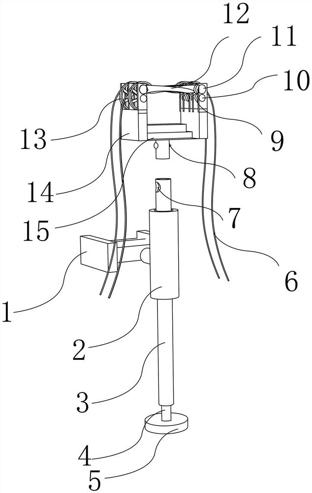
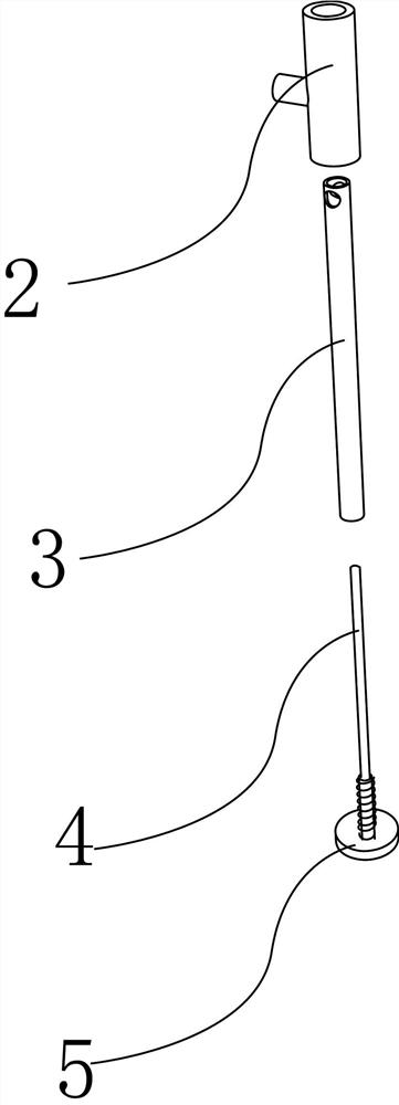
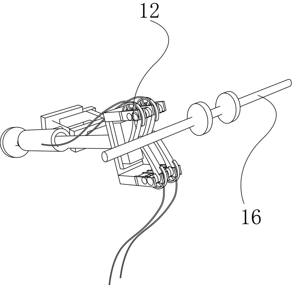
[0036] Such as Figure 1-9 As shown, the short-circuit grounding mechanism of the present invention, the short-circuit grounding mechanism of the present invention includes two parts, that is, a telescopic fixing frame A fixed on the wire tower pylon 17, and a short-circuit grounding device B that can be detachably connected with the telescopic fixing frame, The short-circuit grounding device B can be detachably connected to the telescopic fixing frame A through a connecting mechanism. The telescopic fixed frame A includes a mechanical frame 1 that is movably and fixedly connected with the electric tower. The mechanical frame 1 includes a telescopic rod 1.1 respectively. Set at one end of the steel frame 1.2, adjust the installation rod 1.4 to connect the telescopic rod 1.1, and the middle position of the rotating column 1.3 is provided with a cross bar 1.5;

[0037] The telescopic fixing frame A also includes a telescopic sleeve, which is connected to the rotating column 1.3...

Embodiment 2

[0048] The difference from Embodiment 1 is that when the steel frame 1.2 is installed, it can be connected to the wire tower frame 17 by welding to ensure the stability of the entire device. In addition, the rotating column 1.3 and the cross bar 1.5 in the present application can adopt the form of thread plus an external nut, and it can be finally fixed when the angle can be adjusted. When the rotating column 1.3 and the cross bar 1.5 will stretch After the angle fixing of the sleeve is completed, the positions of the rotating column 1.3 and the cross bar 1.5 can be fixed by welding.


PUM


Abstract

The invention discloses a short-circuit grounding mechanism, which includes a telescopic fixing frame fixed on an electric tower, and a short-circuit grounding device that can be detachably connected with the telescopic fixing frame. The mechanical frame; the telescopic fixed frame also includes a telescopic sleeve, and the telescopic sleeve can be adjusted to be connected to the mechanical frame; the end of the telescopic sleeve can be detachably connected to the short-circuit grounding device; the short-circuit grounding device It includes a concave ground seat, the end of the concave ground seat is provided with a steel claw, and the steel claw is installed on the end of the ground seat through an elastic spring and a hinge, and the elastic spring makes the steel claw Keep a neutral position; the metal part of the ground base is provided with a ground wire. The advantages of the present invention change the disadvantages of manual wiring of the short-circuit grounding device in the past, and cancel the handle end of the short-circuit grounding device. It reduces the situation of manually carrying multiple wire end clips that will not automatically fall off.

Description

technical field [0001] The invention relates to a device for overhauling electric power, in particular to a short-circuit grounding mechanism. Background technique [0002] In the existing short-circuit grounding device, it is a safety tool used to temporarily ground the power equipment that has been powered off when the power equipment is overhauled. Inductive electric effects generated by equipment and lines to prevent the occurrence of electric shock accidents for staff. [0003] Later, people invented a new type of short-circuit grounding device, such as application number: CN200820201388, abstract: a short-circuit grounding device, which is used for safety tools or appliances when overhauling electric equipment, including wire end clamps and electrical inspection devices , the wire end clamp includes a pair of splints that are connected by rotating shafts and are provided with an arc-shaped bite on the upper part. The upper end of one splint is a convex plate, and the ...

Claims


Application Information

Patent Timeline
Patent Type & Authority Patents(China)
IPC IPC(8): H01R11/22G01R19/155H01R4/66H01R13/514
CPCG01R19/155H01R4/66H01R11/22H01R13/514
Inventor 黄景明关越银靖
Owner 柳州大尚科技发展有限公司
Learn More