Short circuit grounding device

A technology of grounding device and wire end clip, which is applied in the direction of electrical connection seat, clip connecting conductor connection, hand-held tool, etc. The effect of low production cost and easy operation

Inactive Publication Date: 2016-08-31
YANTAI MUPING POWER SUPPLY CO OF STATE GRID SHANDONG ELECTRIC POWER CO +1
View PDF4 Cites 0 Cited by
  • Summary
  • Abstract
  • Description
  • Claims
  • Application Information

AI Technical Summary

Problems solved by technology

[0006] The present invention aims at the shortcomings of the prior art that the short-circuit grounding device is easy to fall off during use, poor in safety, and inconvenient to operate, and provides a short-circuit grounding device with better safety, stable structure and convenient operation to solve the above problems

Method used


Image

  • Short circuit grounding device
  • Short circuit grounding device
  • Short circuit grounding device

Examples


Embodiment 1)

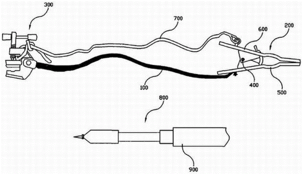
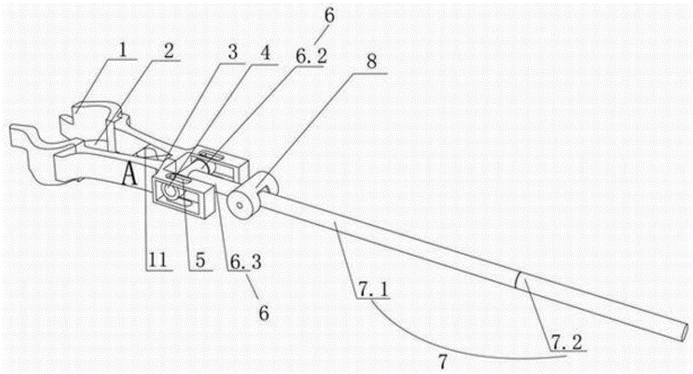
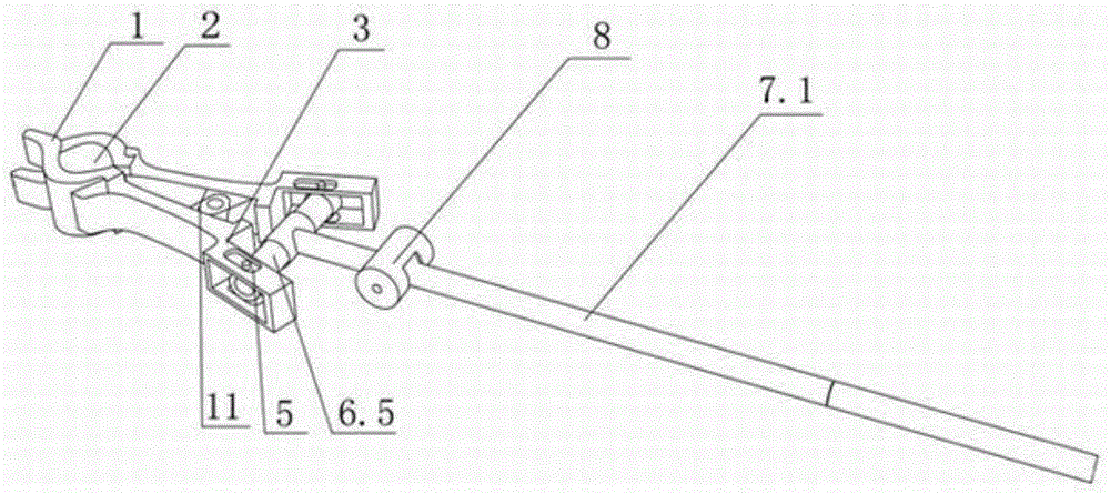
[0026] Such as Figure 2 to Figure 6 As shown, the short-circuit grounding device with good safety, stable structure and convenient operation in this embodiment is a clutch rotary short-circuit grounding device, which includes a wire end clamp A and a grip 7. The wire end clamp A includes a pair of splints 1 connected by a steering shaft via a support piece 11 and provided with an arc-shaped bite 2 on the upper part. The supporting piece 11 is wound with a spring on the rotating shaft 12. The two ends of the spring abut against the inner side walls of the two clamping plates 1. The end of the wire clamp A is provided with a pair of modules 3. A movable nut 4 is provided in the module 3. The movable nut 4 is connected with the movable piece 5 arranged on the counter module 3 through a screw. The movable nut 4 can rotate laterally along the screw. The movable piece 5 can slide on the opposite module 3. The telescopic mechanism 6 includes a pair of telescopic rods 6.1, a cove...

Embodiment 2)

[0030] Such as Figure 7 to Figure 8 As shown, the difference from Embodiment 1 is that: the inner side wall of the splint 1 is also provided with a pressing tongue 13, and the pressing tongue 13 is arranged between the rotating shaft 12 and the arc-shaped bite 2. The other splint 1 is provided with a tongue-depressing through hole correspondingly. The function of the pressure tongue 13 is: when the wire end clamp A is in an open state, the pressure tongue 13 is used to resist the wire end clamp A to prevent the spring force from causing the telescopic rod 6.1 to move back. When it is necessary to loosen the splint 1 for clamping, the pressing tongue 13 contacts the wire, and the wire end clamp A can be released. The rest of the technical principles are the same as in Embodiment 1.

Embodiment 3)

[0032] The difference from the first embodiment is that the telescopic rod 6.1, the rotating rod 6.4, and the grip rod rotating rod 7.3 are all threaded, and the rest of the operation mode is the same as that of the first embodiment.


PUM


Abstract

The invention discloses a short circuit grounding device good in security, stable in structure and convenient to operate. The short circuit grounding device comprises a lead end wire clamp and a grip; the lead end wire clamp comprises a pair of clamping plates, wherein the clamping plates are connected with each other through a rotating shaft in a rotating mode and the upper portion of each clamping plate is provided with an arc-shaped snapping portion; the tail portion of the lead end wire clamp is provided with a pairwise module; a flexible screw cap is arranged in the pairwise module; the flexible screw cap is flexibly connected with the pairwise module and can horizontally rotate and slide in the pairwise module; an extensible mechanism is fixedly connected with the flexible screw cap; the extensible mechanism is connected with the grip; the grip is provided with a control mechanism, wherein the extensible mechanism can be controlled by the control mechanism to extend and retract. According to the short circuit grounding device good in security, stable in structure and convenient to operate, the security performance is high, the lead end wire clamp is manually controlled to clamp or loosen a lead, and accordingly the condition that the lead end wire clamp automatically falls off is avoided.

Description

[0001] The present invention is a divisional application of an invention patent application with an application number of 201210548585.1, an application date of December 18, 2012, and an invention title of "Clutch Rotary Short-circuit Grounding Device". Technical field [0002] The invention relates to a safety tool or appliance for overhauling electric power. Specifically, it relates to a clutch rotary short-circuit grounding device. Background technique [0003] In the existing short-circuit grounding device, such as figure 1 The grounding wire 100 shown is a safety tool used to temporarily ground the power equipment that has been out of power when the power equipment is overhauled. Its purpose is to release the residual charge of the power equipment and prevent sudden calls or nearby live equipment and lines. The induced electric influence is generated to prevent the occurrence of electric shock accidents for staff. Installing the grounding wire is a necessary safety technica...

Claims


Application Information

Patent Timeline
Patent Type & Authority Patents(China)
IPC IPC(8): H01R11/22H01R43/027
CPCB25G1/00B25G1/04H01R11/22
Inventor 柳红兵贺业钊刘绵俊孙朝阳孙健刘妍唐晓宇杨玉健曲磊
Owner YANTAI MUPING POWER SUPPLY CO OF STATE GRID SHANDONG ELECTRIC POWER CO
Why Eureka
Try Eureka