
A motor terminal foot automatic correction mechanism of a motor inspection and correction automatic machine

A terminal foot and automaton technology, applied in the manufacture of motor generators, electromechanical devices, electric components, etc., can solve the problems of low correction efficiency and unstable correction quality of motor terminal feet, and achieve stable and reliable correction quality and high correction efficiency Effect

Active Publication Date: 2022-03-22
DONGGUAN YI CHENG AUTOMATIC EQUIP
View PDF13 Cites 0 Cited by
  • Summary
  • Abstract
  • Description
  • Claims
  • Application Information

AI Technical Summary

Problems solved by technology

[0003] The purpose of the present invention is to overcome the above-mentioned defects in the prior art, and to provide a motor terminal foot automatic correction mechanism of a motor inspection and correction automatic machine, which solves the technology of low correction efficiency and unstable correction quality of the motor terminal foot in the prior art question

Method used


Image

  • A motor terminal foot automatic correction mechanism of a motor inspection and correction automatic machine
  • A motor terminal foot automatic correction mechanism of a motor inspection and correction automatic machine
  • A motor terminal foot automatic correction mechanism of a motor inspection and correction automatic machine

Examples


Embodiment Construction

[0019] In order to make the purpose, technical solutions and advantages of the embodiments of the present invention clearer, the technical solutions in the embodiments of the present invention will be clearly and completely described below in conjunction with the drawings in the embodiments of the present invention. Obviously, the described embodiments It is a part of embodiments of the present invention, but not all embodiments. Based on the embodiments of the present invention, all other embodiments obtained by persons of ordinary skill in the art without creative efforts fall within the protection scope of the present invention.

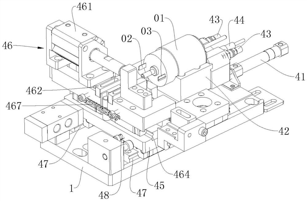
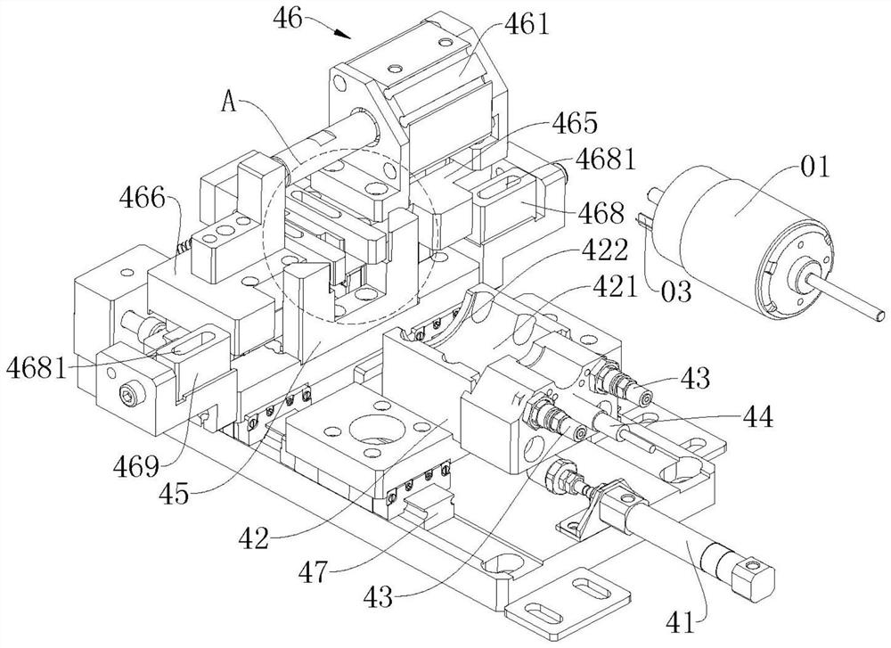
[0020] Such as Figure 1-Figure 4 As shown, the present invention provides a motor terminal foot automatic correction mechanism of a motor inspection and correction automatic machine, including a frame 1, a drive device 41 installed on one side of the frame 1, and a positioning block 42 connected to the drive device 41 , the clamping device 43 in...


PUM


Abstract

The invention discloses an automatic correction mechanism for a motor terminal foot of a motor inspection and correction automaton, comprising a frame, a driving device installed on one side of the frame, and a positioning block connected to the driving device in transmission, installed on one side of the positioning block The tightening device, the sensor installed on the side of the positioning block, the correction reference block installed on the side of the positioning block, the clamping device installed on the side of the correction reference block, the positioning block is provided with a motor limit One side of the motor limit slot is also provided with a positioning step, the correction reference block is provided with a first terminal foot reference part and a second terminal foot reference part, and the clamping device includes a The power part on one side of the block, and the first clamping block and the second clamping block respectively connected to the power part, the power part drives the first clamping block and the second clamping block to move toward or away from each other, and the sensor and The driving device is connected to the signal, and the invention has the advantages of high correction efficiency and stable and reliable correction quality.

Description

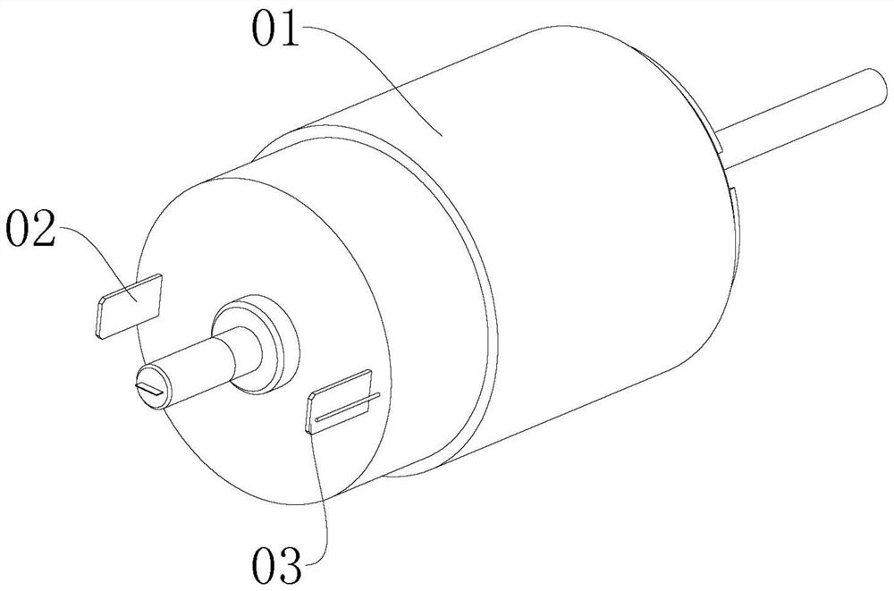
technical field [0001] The invention relates to the field of automatic production of motors with annular protrusions on the outer wall, in particular to a motor terminal foot automatic correction mechanism of a motor inspection and correction automatic machine. Background technique [0002] Such as figure 1 As shown, one side of the motor 01 is provided with a first terminal pin 02 and a second terminal pin 03. In the production process, the roots of the first terminal pin 02 and the second terminal pin 03 are often bent. On the one hand, neither It is beneficial to the subsequent automatic production and affects the appearance of the product, so it needs to be corrected. In the prior art, the correction operation often requires manual operation. Manual operation has technical problems of low correction efficiency and unstable correction quality. Contents of the invention [0003] The purpose of the present invention is to overcome the above-mentioned defects in the prior...

Claims


Application Information

Patent Timeline
Patent Type & Authority Patents(China)
IPC IPC(8): H02K15/00
CPCH02K15/00H02K15/0006
Inventor 袁振海潘其圣
Owner DONGGUAN YI CHENG AUTOMATIC EQUIP
Learn More