
Clamping and locating mechanism and clamping and locating method

A clamping positioning and splinting technology, applied in workpiece clamping devices, manufacturing tools, etc., can solve the problems of insufficient operating space and inability to meet requirements, and achieve the effect of simple structure

Inactive Publication Date: 2016-10-12
BOZHON PRECISION IND TECH CO LTD
View PDF8 Cites 0 Cited by
  • Summary
  • Abstract
  • Description
  • Claims
  • Application Information

AI Technical Summary

Problems solved by technology

For the clamping and positioning of large-sized products, two sets of drive systems are used in the prior art to realize them independently, but in the case of insufficient operating space, the original conventional design can no longer meet the requirements

Method used


Image

  • Clamping and locating mechanism and clamping and locating method

Examples


Embodiment

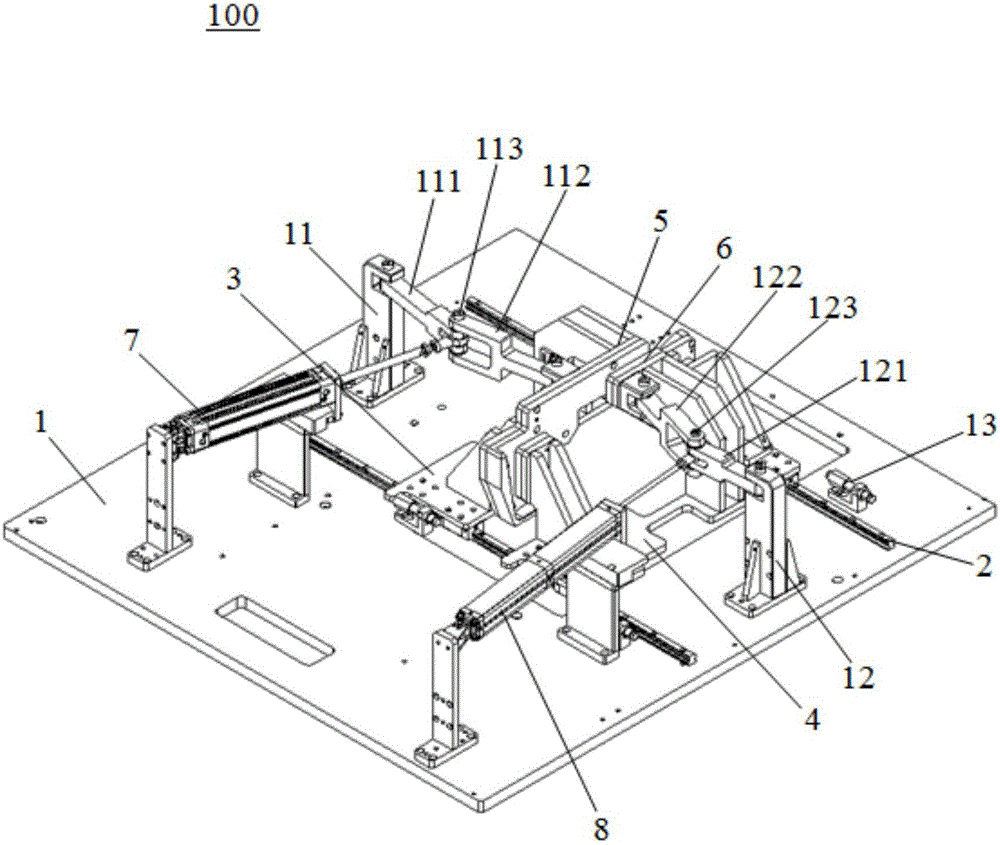
[0022] Please refer to figure 1 , the present embodiment is a clamping and positioning mechanism 100, which includes a support plate 1, a slide rail 2 fixed on the support plate 1, a first connecting plate 3 and a second connecting plate 4 that are movably arranged on the slide rail 2, fixed on the second connecting plate The first clamping plate 5 on a connecting plate 3, the second clamping plate 6 fixed on the second connecting plate 4, the first air cylinder 7 that drives the first connecting plate 3 to slide on the slide rail 2 and drives the second connecting plate 4 in The second cylinder 8 that slides on the slide rail 2. The first cylinder 7 and the second cylinder 8 are located at a certain distance outside the slide rail 2 .

[0023] A first support 11 and a second support 12 are provided on both ends of the slide rail 2 on the support plate 1 . The clamping positioning mechanism 100 also includes a first link 111 movably arranged on the first support 11, a second...


PUM


Abstract

The invention discloses a clamping and positioning mechanism, which includes a support plate, a slide rail fixed on the support plate, a first connecting plate and a second connecting plate movably arranged on the sliding rail, and a second connecting plate fixed on the first connecting plate. A splint, a second splint fixed on the second connecting plate, a first air cylinder driving the first connecting plate to slide on the slide rail, and a second air cylinder driving the second connecting plate to slide on the slide rail. The second air cylinder is multiple The stroke cylinder, the movable rods of the first cylinder and the second cylinder are respectively connected with the first splint and the second splint through connecting rods. The present invention utilizes the connecting rod mechanism to realize the long-distance positioning and clamping function for the product; for the large-sized product in the case of a small operating space, it can realize the integrated functions of storage, positioning and clamping; its structure is simple and can Reserve more operating space for the product, which is very suitable for product positioning problems with insufficient operating space.

Description

【Technical field】 [0001] The invention belongs to the technical field of product clamping, in particular to a clamping and positioning mechanism and a clamping and positioning method. 【Background technique】 [0002] With the continuous development of the manufacturing industry, the application of intelligent equipment is also developing rapidly. Due to the limitation of the enterprise site, the design of more automation equipment should be as simple as possible in structure and low in space occupation. For the clamping and positioning of large-sized products, two sets of drive systems are used in the prior art to realize them independently, but in the case of insufficient operating space, the original conventional design can no longer meet the requirements. [0003] Therefore, it is necessary to provide a new clamping positioning mechanism and clamping positioning method to solve the above problems. 【Content of invention】 [0004] One of the main purposes of the present ...

Claims


Application Information

Patent Timeline
Patent Type & Authority Applications(China)
IPC IPC(8): B25B11/00
CPCB25B11/00
Inventor 吕绍林陈小刚饶元鞠晋
Owner BOZHON PRECISION IND TECH CO LTD
Learn More