
An engine blade positioning and clamping device

An engine blade, positioning and clamping technology, applied to the surface coating liquid device, coating, etc., can solve the problems that the quality cannot be effectively guaranteed, and the glue coating process is difficult to control, so as to improve the production and processing efficiency and facilitate Easy to operate and use

Active Publication Date: 2017-06-09
AECC AVIATION POWER CO LTD
View PDF5 Cites 0 Cited by
  • Summary
  • Abstract
  • Description
  • Claims
  • Application Information

AI Technical Summary

Problems solved by technology

At present, the gluing operation is carried out manually, without special positioning and clamping device, the accuracy is completely guaranteed by manual, the gluing process is difficult to control, and the quality cannot be effectively guaranteed

Method used


Image

  • An engine blade positioning and clamping device
  • An engine blade positioning and clamping device
  • An engine blade positioning and clamping device

Examples


Embodiment Construction

[0026] The present invention will be described in further detail below in conjunction with the accompanying drawings.

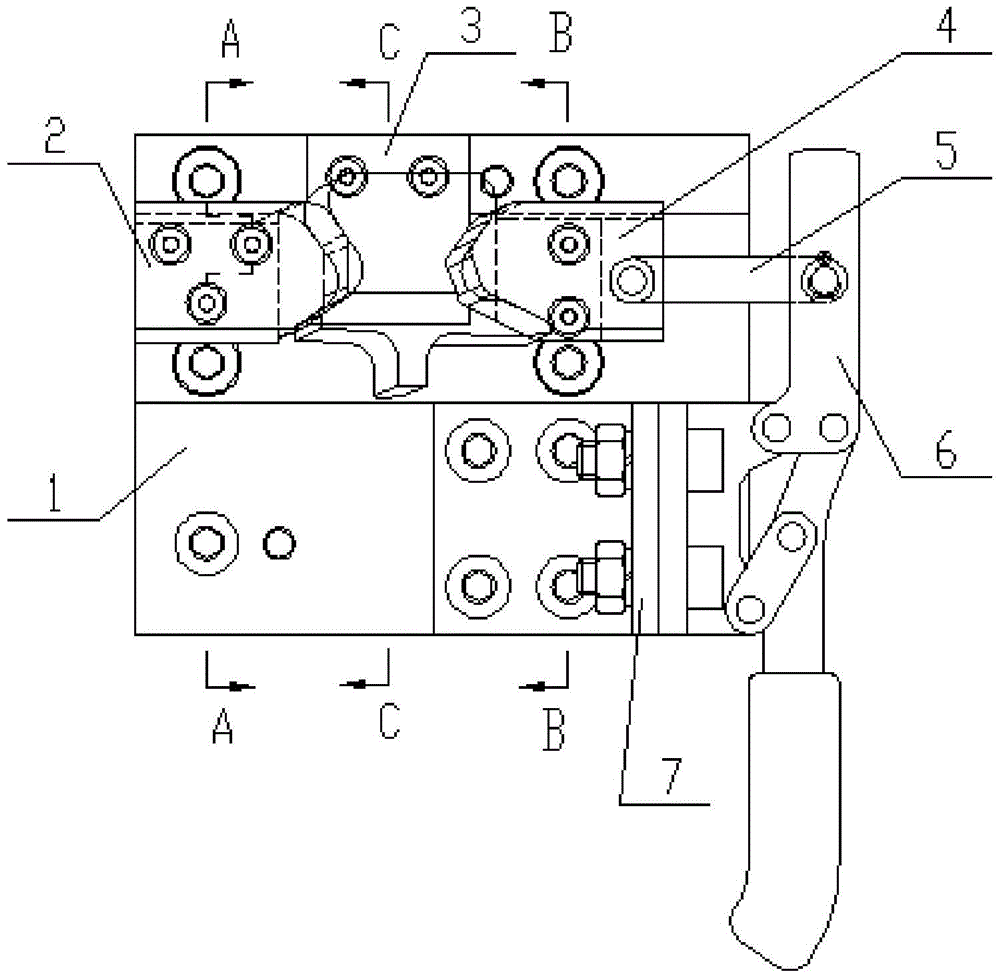
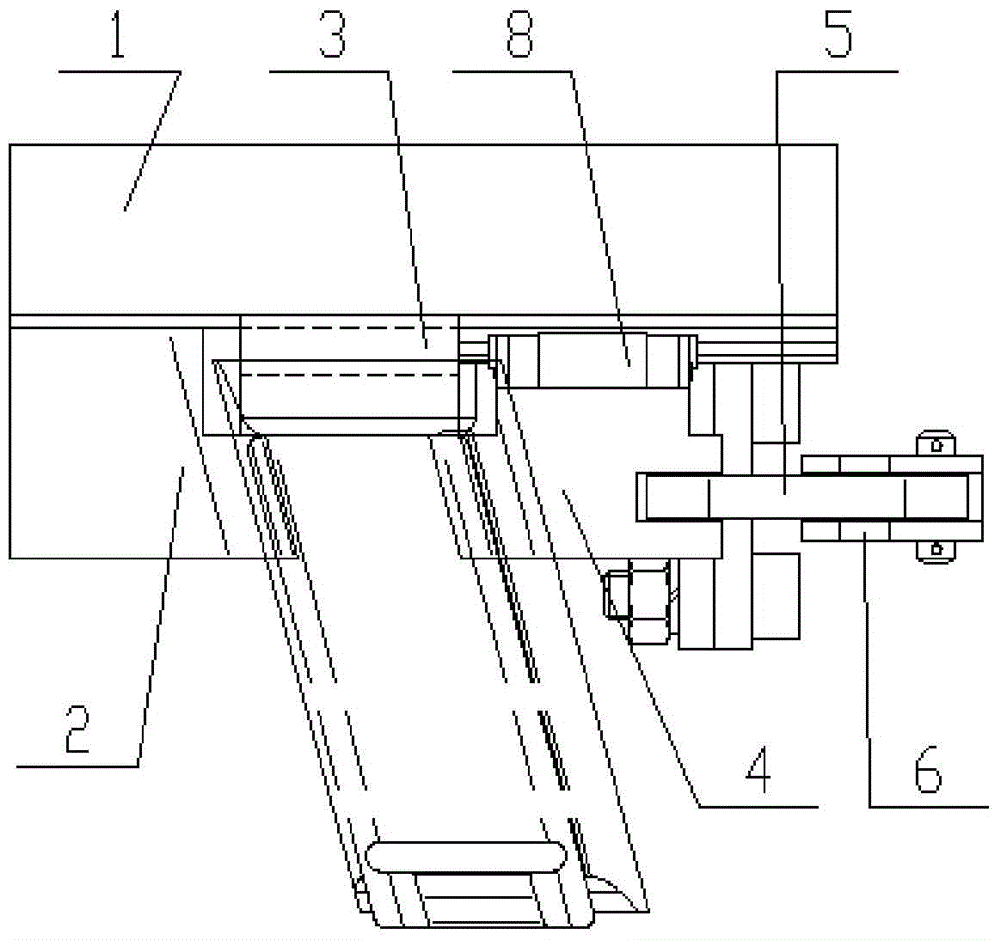
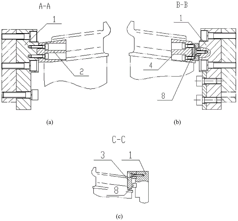
[0027] see Figure 1-5 , the present invention includes a mounting seat 1 provided with a boss surface, and a keyway is opened on the boss surface of the mounting seat 1; several threaded holes 11 and pin holes 12 for connecting with other equipment are provided on the mounting seat 1. The mounting base 1 is provided with a fixed clamping block 2, a positioning block 3 and a sliding clamping block 4 in sequence along the keyway. The sliding clamping block 4 is fixed with a linear bearing 8 for driving it to slide in a straight line, and the sliding clamping block 4 is fixed on a straight line by bolts. On the bearing 8, the linear bearing 8 is fixed on the mounting seat 1.

[0028] see Figure 9 , 11, the sliding clamp block 4 is movably connected to the quick clamp 6 through the slider connecting rod 5, the end of the quick clamp 6 has a corner, and one en...


PUM


Abstract

The invention discloses a positioning and clamping device for engine blades, which comprises a mounting seat provided with a boss surface, and a keyway is provided on the convex surface of the mounting seat; a fixed clamping block, a positioning block and a positioning block are sequentially arranged on the mounting seat along the keyway. The sliding clamping block is fixed with the linear bearing used to drive it to slide linearly; the fixed clamping block and the positioning block position the engine blade, and the blade is clamped by the sliding clamping block. The invention uses the fixed clamp block and the positioning block to position the engine blade, and then uses the sliding clamp block that reciprocates along the linear bearing to clamp the blade. The fixed clamp block and the linear bearing use the same keyway for height direction positioning. The height direction positioning is carried out, the design idea is ingenious, the structure is simple, the positioning and clamping function of the engine blade is realized, the operation is convenient, the use is convenient, and the production and processing efficiency is improved.

Description

technical field [0001] The invention relates to auxiliary equipment for processing engine blades, in particular to a positioning and clamping device for engine blades. Background technique [0002] An aeroengine is an engine that provides the power required for flight by an aircraft. Before the engine blade is assembled, it is necessary to apply glue to the tenon of the blade to meet the needs of specific functions. At present, the gluing operation is carried out manually without special positioning and clamping devices. The accuracy is completely guaranteed by manual work. The gluing process is difficult to control and the quality cannot be effectively guaranteed. Contents of the invention [0003] The purpose of the present invention is to provide a positioning and clamping device for engine blades which has a simple structure and can effectively improve the efficiency and quality of gluing on the tenons of the blades. [0004] In order to achieve the above object, the...

Claims


Application Information

Patent Timeline
Patent Type & Authority Patents(China)
IPC IPC(8): B05C13/02
Inventor 魏敬强刘京春李海燕童小路赵建武田小京柳万珠赵赟
Owner AECC AVIATION POWER CO LTD
Learn More