Static balance eccentric milling fine counterweight process method for pumped storage rotating wheel
A process method and a pumped-storage technology, applied in the field of machinery, can solve the problems of the unbalanced moment index, the influence of the strength of the runner, and the low calculation accuracy, and achieve the effect of improving the efficiency and accuracy of the counterweight.
- Summary
- Abstract
- Description
- Claims
- Application Information
AI Technical Summary
Problems solved by technology
Method used
Image

Examples
Embodiment Construction
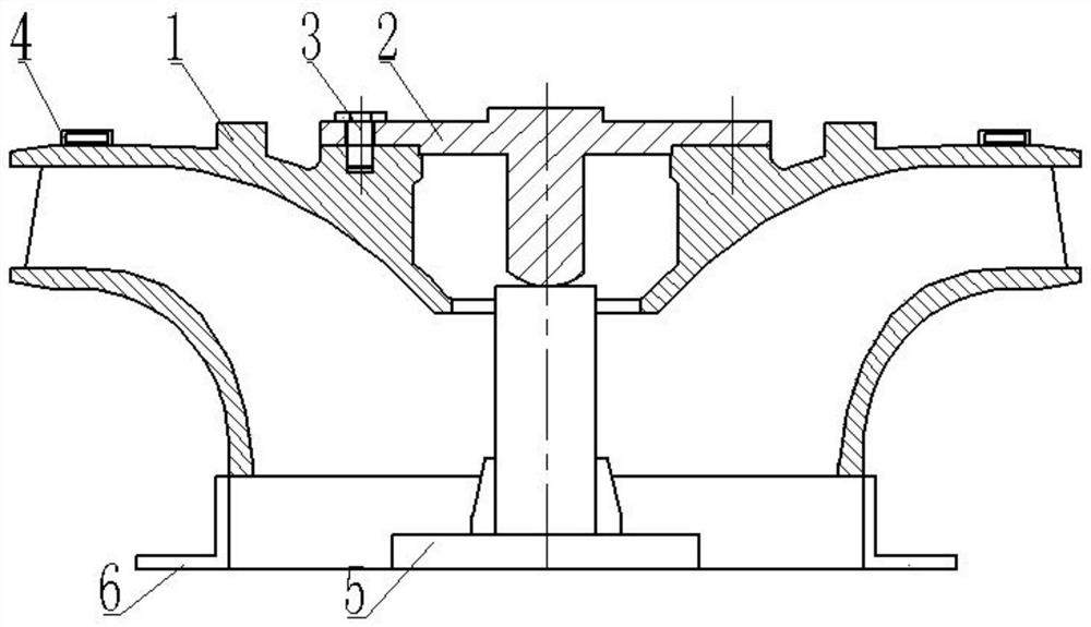
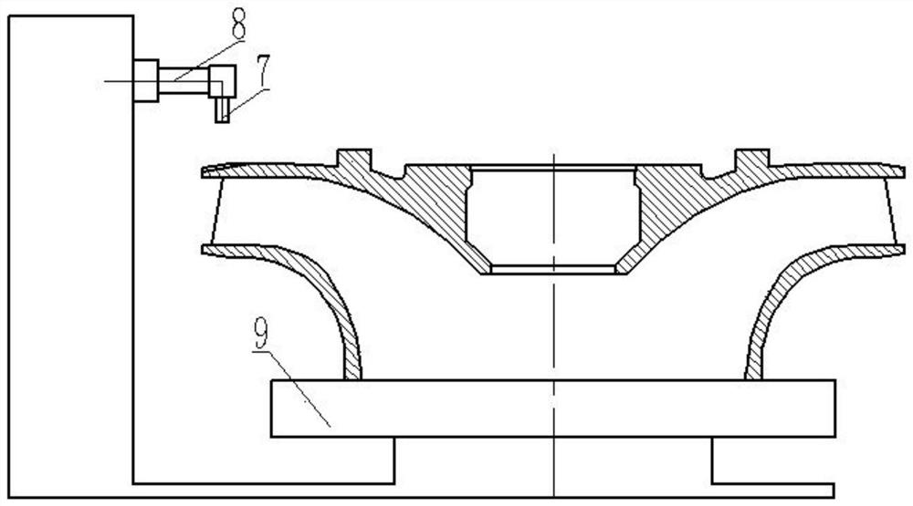
[0053] Such as figure 1 , figure 2 As shown, a water turbine pumped-storage runner static balance partial milling precision counterweight process method, the operation steps are as follows:
[0054] 1) The runner 1 is connected to the balance flange 2 through the connecting bolt 3, and the balance flange 2 is hoisted on the support base 5;
[0055] 2) Measure the distance between the bottom of the runner 1 and the ground at the bottom plane position of the runner 1 using a square 6 circumference, and measure the lowest point of the heavier position of the runner 1, which is the key position of the heavier side of the runner 1, at the key position 180 The ° direction is the light point position of the runner 1, mark the light and key position of the runner 1 on the outer circle side of the plane on the top of the runner 1;
[0056] 3) On the top of the runner 1, place the level ruler 4 evenly distributed in four places, and place the weights at the light position of the runn...
PUM
 Abstract
Description
Claims
Application Information
PatSnap Eureka turns technology decisions into work you can execute. Powered by our Innovation Knowledge Graph, it runs expert workflows across engineering, life sciences, materials and intellectual property. Get your review-ready output in minutes.


