
Pollutant source analysis method and device

A pollutant and pollution source technology, applied in the field of pollution source analysis, can solve problems such as the rough source analysis results of the receptor model, the inability to directly guide the industry's emission reduction measures, and the inability of the PMF model to achieve primary source analysis.

Pending Publication Date: 2020-11-06
3CLEAR SCI & TECH CO LTD
View PDF9 Cites 6 Cited by
  • Summary
  • Abstract
  • Description
  • Claims
  • Application Information

AI Technical Summary

Problems solved by technology

[0003] However, the source apportionment results of the receptor model are relatively rough, which cannot meet the practical application of source apportionment results.
For primary sources, more detailed source analysis is generally required. For example, coal-fired sources can be divided into coal-fired power plants and civil coal-fired, etc., but the PMF model cannot achieve further analysis of primary sources.
For secondary sources, secondary sources are generated by secondary transformation and are not sources of direct discharge, so they cannot be applied to actual control, that is, it is impossible to actually control each pollution source according to the situation of secondary sources
Therefore, it is currently impossible to analyze the refined sources of pollutant emissions, and thus cannot directly guide the industry's emission reduction measures

Method used


Image

  • Pollutant source analysis method and device
  • Pollutant source analysis method and device
  • Pollutant source analysis method and device

Examples


Embodiment Construction

[0046]In order to make the purpose, technical solutions and advantages of the embodiments of the present invention clearer, the technical solutions of the present invention will be clearly and completely described below in conjunction with the accompanying drawings. Obviously, the described embodiments are part of the embodiments of the present invention, not all of them. the embodiment. Based on the embodiments of the present invention, all other embodiments obtained by persons of ordinary skill in the art without making creative efforts belong to the protection scope of the present invention.

[0047] At present, the receptor model PMF is to infer the type of pollution source and its contribution to the receptor by combining the identification components and calculation results of each pollution source when the receptor component spectrum is known but the source spectrum is unknown. Pollution sources are generally divided into primary sources (such as mobile sources, station...


PUM


Abstract

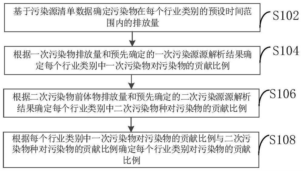
The invention provides a pollutant source analysis method and device, belonging to the technical field of pollution source analysis. The method comprises the following steps: determining the dischargeamount of a pollutant in a preset time range of each industry category based on pollution source list data; determining the contribution ratio of a primary pollutant in each industry category to thepollutant according to the discharge amount of the primary pollutant and a pre-determined primary pollution source analysis result; according to the discharge amount of a secondary pollutant precursorand a pre-determined secondary pollutant source analysis result, determining the contribution ratio of secondary pollutant species in each industry category to the pollutant; determining the contribution ratio of each industry category to the pollutant according to the contribution ratio of the primary pollutant in each industry category to the pollutant and the contribution ratio of the secondary pollution species in each industry category to the pollutant; and through combination of the contribution ratio of each industry category to the pollutant with a receptor model and a pollution source list, establishing a pollution source contribution system of secondary sources, primary sources and various industries. Thus, a source analysis result output by the receptor model can guide industrial emission reduction measures.

Description

technical field [0001] The invention relates to the technical field of pollution source analysis, in particular to a pollution source analysis method and device. Background technique [0002] At present, the source of air pollution sources is generally analyzed through the receptor model PMF (Positive Matrix Factorization). Industrial sources, dust sources) and secondary sources. [0003] However, the source apportionment results of the receptor model are relatively rough, which cannot meet the practical application of the source apportionment results. For primary sources, more detailed source analysis is generally required. For example, coal-fired sources can be divided into coal-fired power plants and civil coal-fired, etc., but the PMF model cannot achieve further analysis of primary sources. For secondary sources, secondary sources are generated by secondary transformation and are not a source of direct discharge, so they cannot be applied to actual control, that is, i...

Claims


Application Information

Patent Timeline
IPC IPC(8): G16C20/70G01N33/00G01N15/06
CPCG01N15/06G01N33/0037G01N33/0042G01N33/0054G16C20/70
Inventor 李蔷秦东明孙明生易志安李诗瑶李璇张言云杨帆管梦爽
Owner 3CLEAR SCI & TECH CO LTD
Learn More