NFC device
A technology of connection structure and switching part, applied in electrical components, transmission systems, near-field transmission systems, etc., can solve problems such as easy loss, and achieve the effect of being easy to carry and use
- Summary
- Abstract
- Description
- Claims
- Application Information
AI Technical Summary
Problems solved by technology
Method used
Image


Examples
Example Embodiment
[0033] Example one
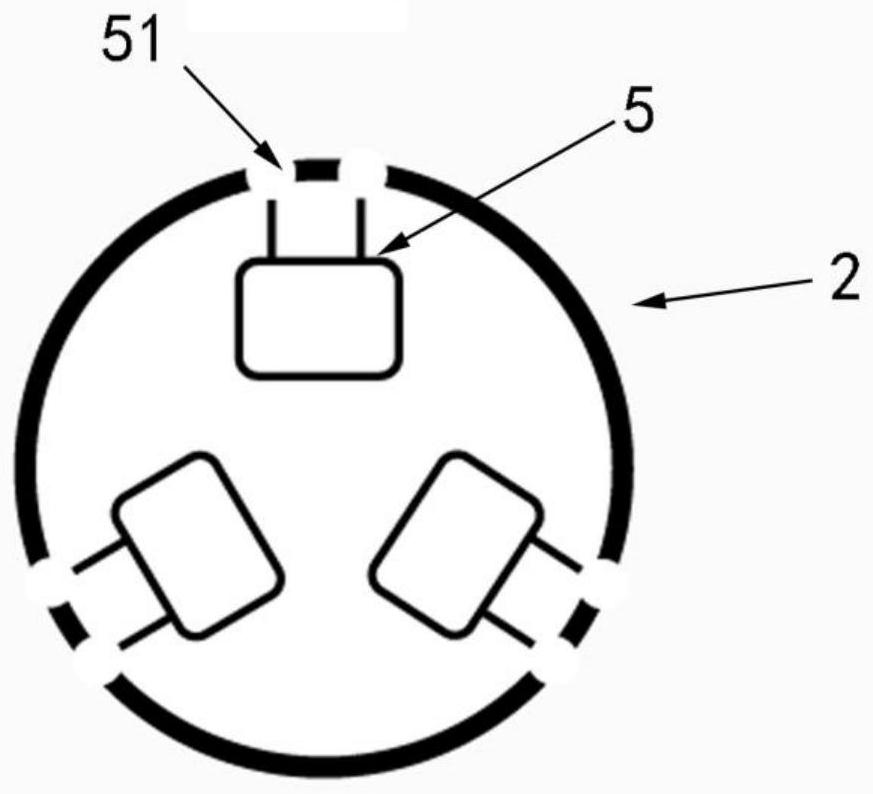
[0034] Such as figure 1 In the illustrated embodiment, the first connecting structure 1 includes a first connecting portion 11 and a second connecting portion 12. The induction coil 3 is installed in the first connecting portion 11; the first connecting portion 11 and the second connecting portion 12 Through the connection of the first switching portion 4, the first connecting portion 11 can rotate with respect to the second connecting portion 12 with the first switching portion 4 as a connection point, so that the first connecting portion 11 and the second connecting portion 12 have Included angle. Such as figure 2 In the example shown, three second switching parts 5 are installed on the second connection structure 2, and one NFC chip is installed in each of the second switching parts 5. It should be noted that the second connection structure 2 is installed with 3 The number of second switching parts 5 is only an embodiment, and the number of second switch...
Example Embodiment
[0037] Embodiment two
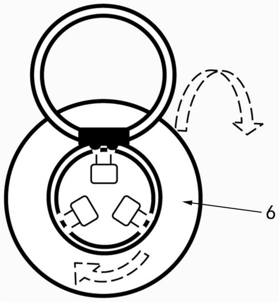
[0038] As a modification of the first embodiment, the structural components are the same as those of the first embodiment. The difference is that the second connecting portion 12 is fixed, and the second connecting structure 2 as a whole can be clockwise or counterclockwise relative to the second connecting portion 12 Rotate so that the second switching part 5 and the first switching part 4 can move relatively. When the first switching part 4 is connected to one of the second switching parts 5, the NFC chip corresponding to the second switching part 5 start up. Other structural components and principles are similar to those of the first embodiment, and will not be repeated here.
Example Embodiment
[0039] Embodiment three
[0040] Such as Figure 5 In the example shown, the second connecting structure 2 is a hard insulating planar structure, which can be made of hard plastic and other materials. The first connecting structure 1 is a flexible insulating structure, which can be made of soft cloth or leather. The induction coil 3 is installed in the second connection structure 2. It can be understood that the two ends of the induction coil 3 are placed in the interlayer of the first connection structure 1. The second connection structure 2 is provided with a rail 7, the first connection structure 1 is provided in the rail 7, one end of the first connection structure 1 is a first fixed end 13, and the other end is a first free end. At the end 14, the first fixed end 13 is fixedly connected to the second connecting structure 2, and the first free end 14 can move along the track 7, thereby driving the first switching portion 4 along the track 7. Moving, the second switching par...
PUM
 Abstract
Description
Claims
Application Information
 - R&D Engineer
- R&D Manager
- IP Professional
- Industry Leading Data Capabilities
- Powerful AI technology
- Patent DNA Extraction
Browse by: Latest US Patents, China's latest patents, Technical Efficacy Thesaurus, Application Domain, Technology Topic.
© 2024 PatSnap. All rights reserved.Legal|Privacy policy|Modern Slavery Act Transparency Statement|Sitemap