
Underslung spin lock locking device and using method

A technology of locking device and locking groove, which is applied in the direction of load fixing, transportation and packaging, and vehicles used for freight transportation, etc. It can solve the problem of affecting the transportation safety of the transportation platform and vehicle cabin, increasing the uncertainty of locking, and the lock of the twist lock is not in place. and other problems, to achieve the effect of intuitive and convenient observation, simple structure and high reliability

Pending Publication Date: 2020-11-10
江苏捷诚车载电子信息工程有限公司
View PDF0 Cites 2 Cited by
  • Summary
  • Abstract
  • Description
  • Claims
  • Application Information

AI Technical Summary

Problems solved by technology

The existing twist locks are divided into bottom-hung type and top-hung type. The top-hung type can be judged by the direction of the handle whether the lock is securely locked. The bottom-hung type can only be detected by observing the direction of the lock tongue in the corner Judgment, Inconvenience to Observation Increases Lock-in Uncertainty
Especially when there are mounting parts such as leveling devices and lifting mechanisms installed on the corner fittings, it will make observation more inconvenient, or the state of the lock tongue cannot be observed, and there is a hidden danger that the twist lock will not be locked in place, seriously affecting the transportation platform and the vehicle. cabin transport safety

Method used


Image

  • Underslung spin lock locking device and using method
  • Underslung spin lock locking device and using method
  • Underslung spin lock locking device and using method

Examples


Embodiment Construction

[0027] Below in conjunction with accompanying drawing and the embodiment that the present invention is installed on the vehicle, the present invention will be further described.

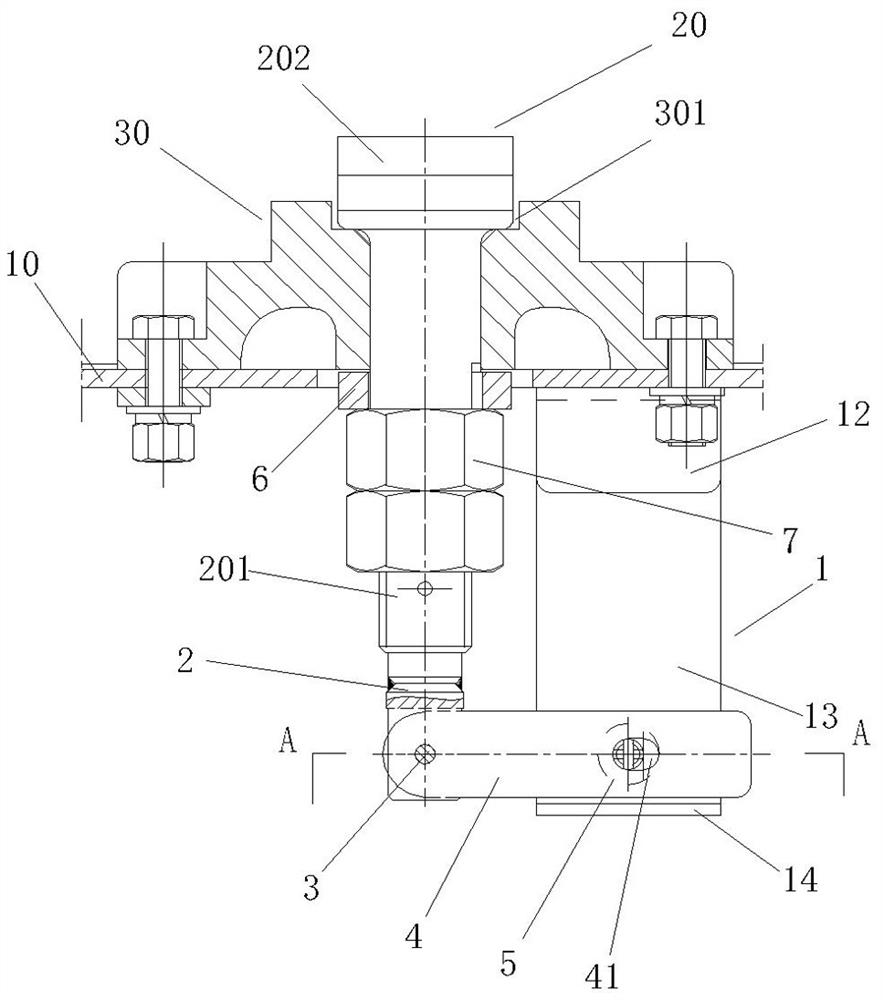
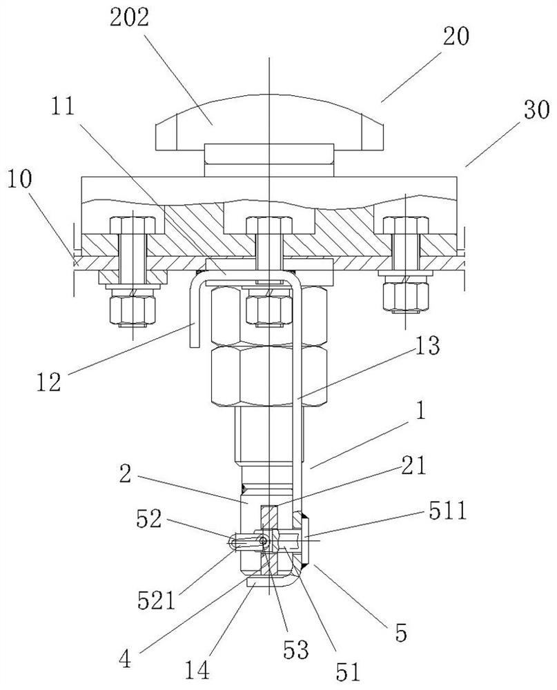
[0028] Such as figure 1 and figure 2 As shown, this embodiment includes a fixed support 1, a connecting seat 2, a shaft pin 3, a lock plate 4 and a lock plate locking mechanism 5, the fixed support 1 is an inverted L-shaped bending structure, and the L-shaped short side 11 is downward Bending the vertical side 12, the L-shaped long side 13 is bent toward the vertical side 12 to form the horizontal side 14, and the L-shaped short side 11 is welded and fixed on the lower side of the transport platform 10, and is located at figure 1 The right side of the lock bar 201 of the middle and lower suspension type twist lock 20.

[0029] The upper end of the connecting seat 2 is welded and fixedly connected with the lower end of the locking bar 201 of the downwardly suspended twist lock 20, so that the conne...


PUM


Abstract

The invention discloses an underslung spin lock locking device which comprises a fixed support, a connecting base, a shaft pin, a lock plate and a lock plate locking mechanism, the fixed support is fixed to the lower side face of a transportation platform, the upper end of the connecting base is fixedly connected with the lower end of a lock rod of an underslung spin lock, and one end of the lockplate is hinged to the lower end of the connecting base; and one end of the locking plate locking mechanism is fixed on the lower part of the fixed support. When the spin lock is locked, the middle ofthe lock plate penetrates through the other end of the lock plate locking mechanism to be locked in the lower end of the fixed support. And when the spin lock is unlocked, the lock plate is separatedfrom the lock plate locking mechanism and suspended below the lower end of the connecting seat. The method comprises the steps that A1, the spring bolt moves upwards to be disengaged from the lockinggroove, A2, the spring bolt is unlocked, B1, the spring bolt falls into the locking groove, and B2, the spring bolt is fixed into the locking groove. The structure is simple, whether the spring boltis in a locked state or an unlocked state can be accurately judged, the fault that spin locking is not in place is avoided, and transportation safety of the vehicle-mounted shelter is guaranteed.

Description

technical field [0001] The invention relates to a connection and locking device for a vehicle-mounted shelter and a carrying platform, in particular to a connection and locking device and a locking or unlocking method for connecting corner fittings at the bottom four corners of a vehicle-mounted shelter and a rotary lock for a carrying platform, and belongs to the field of shelter accessories. Background technique [0002] The vehicle-mounted shelter is a kind of box equipment installed on the transportation platform for field work and combat. When in use, it needs to be unloaded from the transportation platform to the ground; during transportation, it is loaded from the ground to the transportation on the vehicle. In order to ensure that the vehicle-mounted shelter can be stably fixed on the transportation platform, the corner fittings at the bottom four corners of the vehicle-mounted shelter and the transportation platform are fixedly connected by special twist locks. The...

Claims


Application Information

Patent Timeline
Patent Type & Authority Applications(China)
IPC IPC(8): B60P7/13
CPCB60P7/132
Inventor 冉龙发朱翔许建张登月
Owner 江苏捷诚车载电子信息工程有限公司
Learn More