Loudspeaker module and sound generating device

A loudspeaker module and filling technology, which is applied in the field of loudspeakers, can solve problems such as poor gas adsorption effect of sound-absorbing materials, affecting the acoustic performance of the loudspeaker module, and the limitation of sound cavity space expansion, so as to achieve improved acoustic performance, smooth circulation, and high-quality Good results

Active Publication Date: 2021-01-22
GOERTEK INC
View PDF4 Cites 0 Cited by
  • Summary
  • Abstract
  • Description
  • Claims
  • Application Information

AI Technical Summary

Problems solved by technology

[0002] With the development of social economy and the improvement of living standards, consumers have higher requirements for mobile phone audio performance indicators, which requires more mobile phone space for sound cavity design, but the contradiction is that the client also has It is required that the mobile phone should be as light and thin as possible, improve the grip feeling, and be easy to carry. Therefore, the expansion of the sound chamber space is limited, and even needs to be compressed
[0003] In recent years, in order to expand the volume of the sound cavity, speaker module manufacturers have adopted the method of filling sound-absorbing particles in the existing sound cavity. Without expanding the physical volume of the sound cavity, the equivalent volume of the audio rear cavity has been increased. The room and the sound cavity are connected by inserting mesh cloth, but only the isolation mesh cloth in the entire filling room can allow the airflow to enter and exit, and the airflow at the far end is not smooth, resulting in poor gas adsorption effect of the sound-absorbing material, which affects the speaker module. Group Acoustic Performance

Method used


Image

  • Loudspeaker module and sound generating device
  • Loudspeaker module and sound generating device
  • Loudspeaker module and sound generating device

Examples


Embodiment Construction

[0033] The following will clearly and completely describe the technical solutions in the embodiments of the present invention with reference to the accompanying drawings in the embodiments of the present invention. Obviously, the described embodiments are only part of the embodiments of the present invention, not all of them. Based on the embodiments of the present invention, all other embodiments obtained by persons of ordinary skill in the art without making creative efforts belong to the protection scope of the present invention.

[0034] It should be noted that all directional indications (such as up, down, left, right, front, back...) in the embodiments of the present invention are only used to explain the relationship between the components in a certain posture (as shown in the figure). Relative positional relationship, movement conditions, etc., if the specific posture changes, the directional indication will also change accordingly.

[0035] In addition, the descriptio...


PUM


Abstract

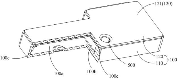
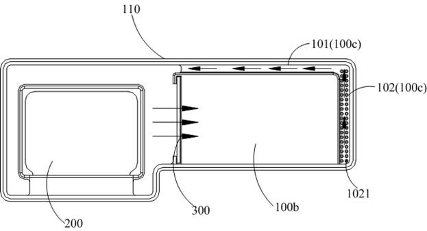
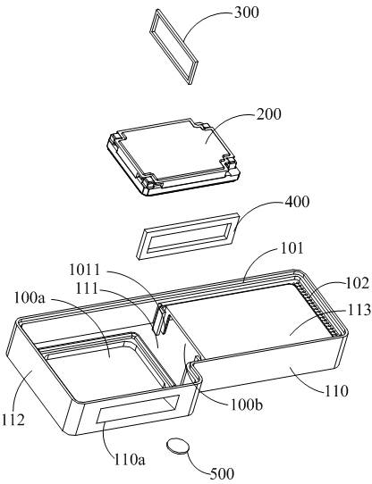
The invention discloses a loudspeaker module and a sound production device, and the loudspeaker module comprises a shell assembly, a loudspeaker unit, a sound absorption part, and a ventilation isolation part, and the shell assembly is provided with an installation cavity; the loudspeaker unit is installed in the installation cavity and forms a first sound cavity and a second sound cavity which are communicated with each other with the shell assembly in an enclosing mode, and a filling chamber is arranged in the second sound cavity; the filling chamber is filled with the sound absorption part;a communicating opening is formed in one side, close to the first sound cavity, of the filling chamber; the ventilation isolation part is arranged on the communicating opening; an air flow channel isdefined by the chamber wall of the filling chamber and the inner wall of the shell assembly, the air flow channel communicates with the first sound cavity, and at least one end, away from the ventilation isolation part, of the air flow channel is provided with a vent hole communicating with the filling chamber. According to the loudspeaker module, the filling area structure of the loudspeaker module is improved, the contact effect of airflow and the sound absorption part is better, and the acoustic performance is improved.

Description

technical field [0001] The invention relates to the technical field of loudspeakers, in particular to a loudspeaker module and a sounding device. Background technique [0002] With the development of social economy and the improvement of living standards, consumers have higher requirements for mobile phone audio performance indicators, which requires more mobile phone space for sound cavity design, but the contradiction is that the client also has It is required that the mobile phone should be as light and thin as possible to improve the grip feeling and be easy to carry. Therefore, the expansion of the sound chamber space is limited, and even needs to be compressed. [0003] In recent years, in order to expand the volume of the sound cavity, speaker module manufacturers have adopted the method of filling sound-absorbing particles in the existing sound cavity. Without expanding the physical volume of the sound cavity, the equivalent volume of the audio rear cavity has been i...

Claims


Application Information

Patent Timeline
Patent Type & Authority Patents(China)
IPC IPC(8): H04R9/06H04R9/02
CPCH04R9/02H04R9/06
Inventor 申兆垒陈阿亮
Owner GOERTEK INC
Why Eureka
Try Eureka