[0020] Embodiments of the present invention is described in detail below, exemplary embodiments of the embodiment shown in the accompanying drawings, wherein same or similar reference numerals designate the same or similar elements or functionally similar or identical elements are provided with. By following with reference to the embodiments described are exemplary, and are intended for explaining the present invention and should not be construed as limiting the present invention.
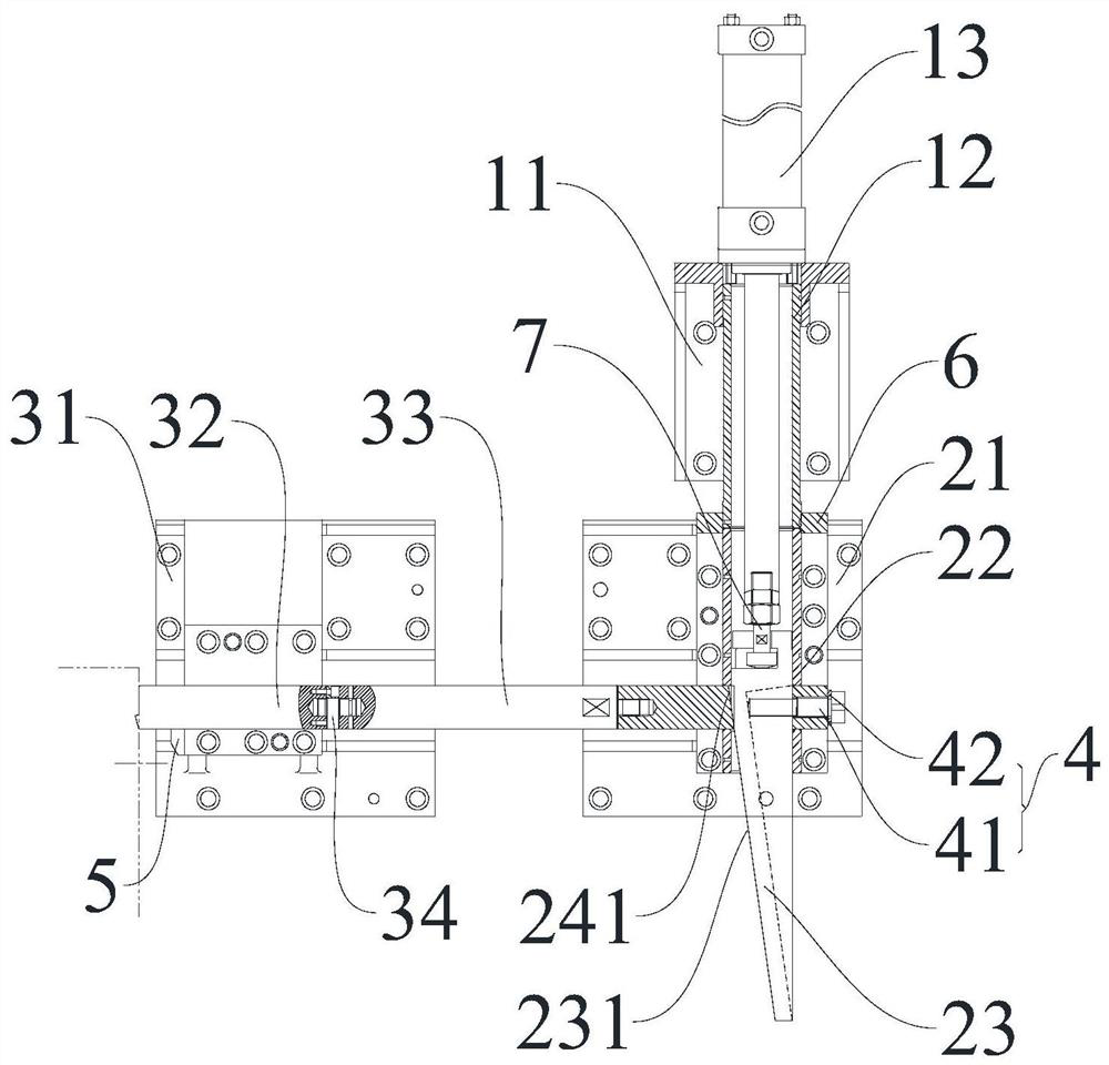
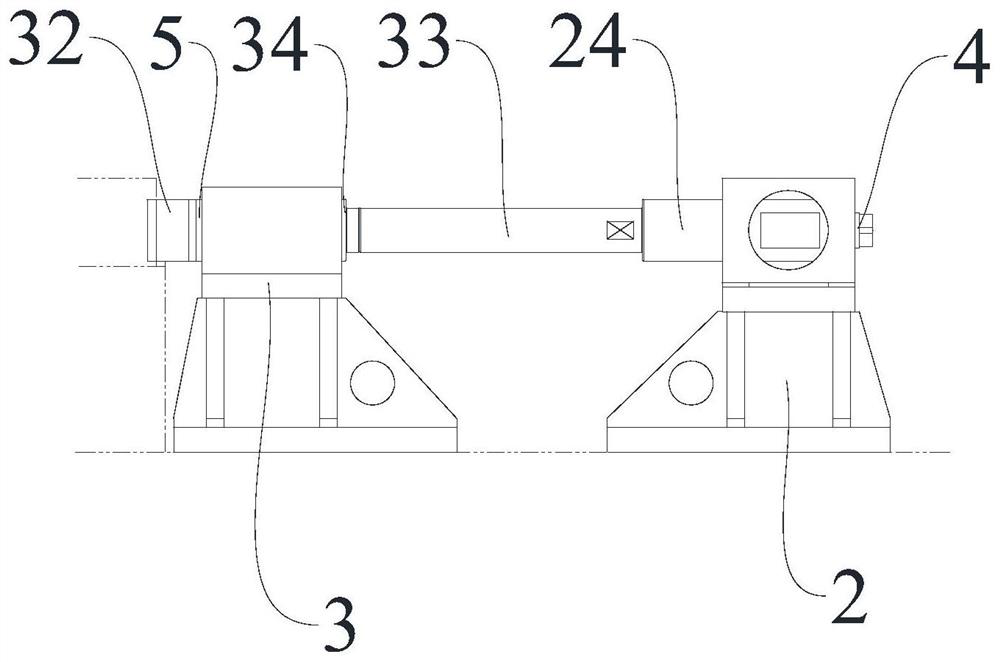
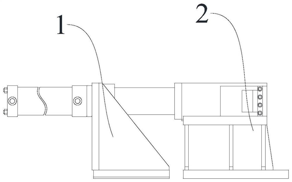
[0021] like Figure 1 to 4 As shown in a longer effective stroke of the sub-feed side of the top wedge structure, comprising a propulsion assembly 1, push in the front assembly 1 is provided with a locking assembly 2, the locking assembly 2 is provided with a top side of the locking assembly 3 disposed perpendicular thereto , lock assembly 2 comprises a second mounting base 21, a second guide sleeve 22, plunger 24 and wedges 23, the second guide sleeve 22 is provided on the second mounting base 21, wedges 23 inserted in the second guide sleeve 22 and a piston rod connected to the propulsion assembly 1 in advance of the cylinder 13, wedges 23 side toward the top tight assembly 3 is first slope 231 having a predetermined locking angle, one end of the push rod 24 projects into the second guide inner sleeve 22, this end of the push rod 24 is provided with a square hole, the square hole passing through the wedge bar 23 of the plunger 24, the plunger 24 is provided with a square hole into contact with the second inclined surface 231 against the first inclined surface 241, push the other end of the rod tightening assembly 3 is connected to the top 24, by advancing the stretching rod assembly 1 is driven by the wedge 23, which in turn pushes the push rod 24 to drive the top tight assembly reciprocates linearly 3, wherein the top tight assembly 3 comprises a third mounting seat 31, a top lever 32 and the connecting shaft 33, the third mount 31 and the second mounting seat 21 disposed spaced apart, one end of the jack plug 32 on the third mounting seat 31, the top surface of the other end of the top 321 is provided with a predetermined angle the connecting shaft 33 connected to an end of the push rod 24, the other end of the connecting shaft 33 and the ram 32 is connected by a connecting flange 34, wherein the connection flange 34 is provided on the jack 32, the jack 32 is a rectangular, rigid guide , deformation of the steel sheet will not generate rotational force, effectively overcome the deformation of the sub-material; propulsion assembly 1 comprises a first mounting base 11, a first guide sleeve 12 and the advancing cylinder 13, a first mount 11 and second mount 21 disposed spaced apart, the first guide sleeve 12 is provided on the first mounting seat 11 and having one end engaged with the second guide sleeve 22, advancing cylinder 13 is provided at the other end of the first guide sleeve 12.
[0022] One kind of the stroke of the invention effectively elongated wedge side of the top sub-feed configuration, with the locking assembly 2 arranged perpendicular to each other and separated from the top tight assembly 3, and using the extended wedges 23 and propulsion cylinder 13, the rod 23 and the wedge advancing cylinder 13 is provided at a position away from the steel sheet and to avoid saw blade member near a third plate mounting base 31 are small, so that the wedge block sub-feed effective stroke longer side of the roof structure, and the jack 32 from the top tight position closer kerf. In use, when the steel sheet to the position, advancing piston rod 13 of the cylinder rod 23 moves wedge push and drive the plunger 24 toward the direction perpendicular to the wedges 23, 34 by a connecting shaft so that the jack 33 and the connecting flange 32 and pressed against the projecting side surface of the sub-material, wherein the top ram 32 is provided with a top 321, may feed into the top surface of the sub better prevent deformation to enhance the effect of the top side, the wedges 23 and 24 in contact with the plunger the two surfaces are provided with an inclined surface of the same inclination, and the self-locking angle, the jack 32 to ensure the force due to deformation of the steel sheet will not be retracted, while the jack 32 is a rectangular, rigid guide, not rotation occurs, thereby effectively overcoming the force of the deformation of the sub-material, and reducing the probability of occurrence of the clamp cutter device failure rate, extend the life cycle of the saw blade. The mechanism of the very long wedges, but far away from the steel sheet, does not interfere with the blade member and the circular sawing machine, and the smaller volume of the top tight assembly 3, close to the jack from the kerf, so can ensure a top long stroke locking assembly 3, the top side and can achieve better results, and a minimum width of small substreams, improve production efficiency of the enterprise.
[0023] like figure 1 and figure 2 , The second guide sleeve 22 is provided on the assembly 4 is retracted, the retraction assembly 4 comprises a screw 41 and the adjustment pad ring 42, screw 41 is connected to the push rod 24, and the bottom end of the screw rod 41 and the wedge 23 is parallel to the plane of the first inclined surface 231 abuts, i.e. on that side facing away from and parallel to the first inclined surface 231, the adjustment screw 41 is mounted a grommet 42, grommet 42 provided in the adjusting head 41 of the plunger 24 and the screw between easy adjustment of the gap between the bottom end 23 of the screw 41 wedges, by the use of retractable assembly 4 to be driven by the push rod 24 and the jack 32 is retracted when the wedge 23 retracted.
[0024] like figure 1 , The first slope 231 and second slope 241 bevel angle range is 4 to 12 degrees, it is understood that the self-locking angle is preferably an angle of 8 degrees, the deformation force can overcome the sub-material.
[0025] like figure 1 and Figure 4As shown, the angle range of the top 321 is 40 to 120 degrees, preferably an angle of 90 degrees, wherein the angle facing the sub-material is α degree, the α is preferably 15 degrees, and the angle towards the masterbatch is β degree, beta is preferred. 75 degrees to effectively act in the direction of the subjunction, effectively prevent the substance to the masterbatch direction.
[0026] like figure 1 and figure 2 As shown, the third mount 31 is provided with a fixed baffle 5 toward the top of the top 321, it is to be understood that the fixed baffing 5 is disposed on one side of the saw blade, and the position is higher than the top 321 retracted To ensure that the steel sheet does not touch the top 321 when the sheet is fed, it is contemplated to protect the top 321.
[0027] like figure 1 As shown, the connection of the first guide sleeve 12 and the second guide sleeve 22 can be connected by the transition flange 6, and can be easily connected to the first guide sleeve 12 and the second guide sleeve 22 through the transition flange 6. The coaxial degree between the first guide sleeve 12 and the second guide sleeve 22 improves the mechanism of work reliability.
[0028] like figure 1 As shown, the wedge rod 23 is connected to the piston rod, and it is to be understood that the bottom end of the wedge rod 23 is provided with an opening in the radial direction, and the connecting lock rod 7 is in the opening and the wedge bar 23 The piston rod is connected together, and the wedge rod 23 and the piston rod are short and convenient.
[0029] like Figure 1 to 4 As shown, the top rod 32 and the push rod 24 are both a rectangular cuboid, the guided rigidity, and high reliability.
[0030] Although the embodiments of the present invention have been shown and described above, it is understood that the above-described embodiments are exemplary, and cannot be understood as limiting the invention, and those of ordinary skill in the art can be described above. EXAMPLES Change, modify, replace, and variations.