

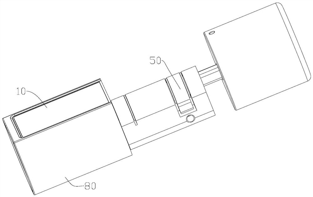
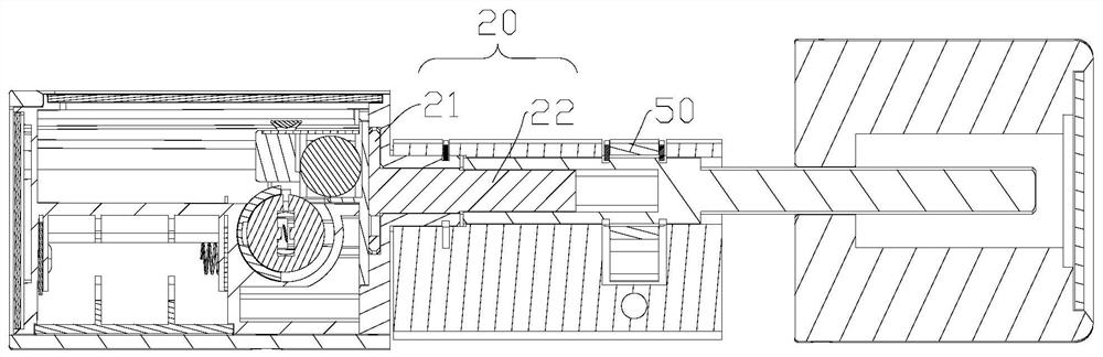
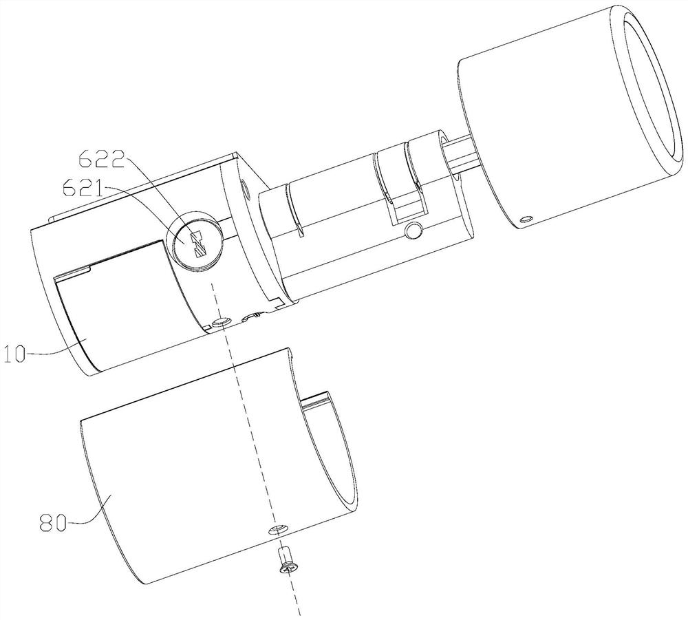
Lock linkage structure and lock
A linkage mechanism and linkage technology, applied in the field of locks, can solve the problems of low safety factor and inability to unlock with explosion-proof force, and achieve the effect of preventing violent unlocking
- Summary
- Abstract
- Description
- Claims
- Application Information
AI Technical Summary
Problems solved by technology
Method used
Image

Examples
Embodiment approach 1
[0039] Embodiment 1: The cross section of the linkage hole 100 is a polygon, such as a square, a rectangle, etc. Correspondingly, the cross section of the first linkage rod 31 is a polygon that matches the linkage hole 100;
Embodiment approach 2
[0040] Embodiment 2: a block protrudes from the first linkage rod 31, and a slot for inserting the block is provided on the linkage hole 100, so that when the first linkage rod 31 rotates with the handle 10, the block pushes the slot The groove wall, so as to link the transmission member 20; Embodiment 3: as Figure 5-6 As shown, the linkage hole 100 is arranged eccentrically with the handle 10, that is, the central axis of the linkage hole 100 is staggered from the central axis of the handle 10; more specifically, the linkage hole 100 is a round hole, and the first linkage rod 31 is cylindrical; The third preferred embodiment of the present invention is easier to process.
[0041] The above-mentioned rotating part 321 can be an existing lock cylinder. In the present invention, the rotating part 321 is preferably the output shaft of the motor 32, and the body of the motor 32 is installed on the handle 10. In this way, the handle 10 can only be realized by controlling the motor...
PUM
 Abstract
Description
Claims
Application Information