X-ray flaw detection automatic calibrating device

An automatic verification and X-ray technology, which is applied in the field of X-ray flaw detection, can solve the problems of no storage, the position height cannot be adjusted, the X-ray flaw detection instrument cannot be used normally, etc., and the effect of saving time and effort is achieved.

Active Publication Date: 2020-11-24
大冶市探伤机有限责任公司
View PDF19 Cites 1 Cited by
  • Summary
  • Abstract
  • Description
  • Claims
  • Application Information

AI Technical Summary

Problems solved by technology

[0003] In order to ensure that the internal quality of metal material items is qualified, X-ray flaw detection methods will be used when performing internal inspections of metal material items. The traditional X-ray flaw detector has a single shape and structure. When in use, the position and height cannot be adjusted for support, and manual adjustment is required. And when the items are placed, it is necessary to adjust the use height of the placed items manually, which leads to certain limitations in the operation of the X-ray flaw detection method, and after the X-ray flaw detection instrument is used, there is no reasonable storage, resulting in the X-ray flaw detection instrument often Knocking damage will lead to the loss of X-ray flaw detection equipment. In severe cases, the X-ray flaw detection instrument cannot be used normally, resulting in errors in the verification of X-ray flaw detection equipment

Method used


Image

  • X-ray flaw detection automatic calibrating device
  • X-ray flaw detection automatic calibrating device
  • X-ray flaw detection automatic calibrating device

Examples


Embodiment Construction

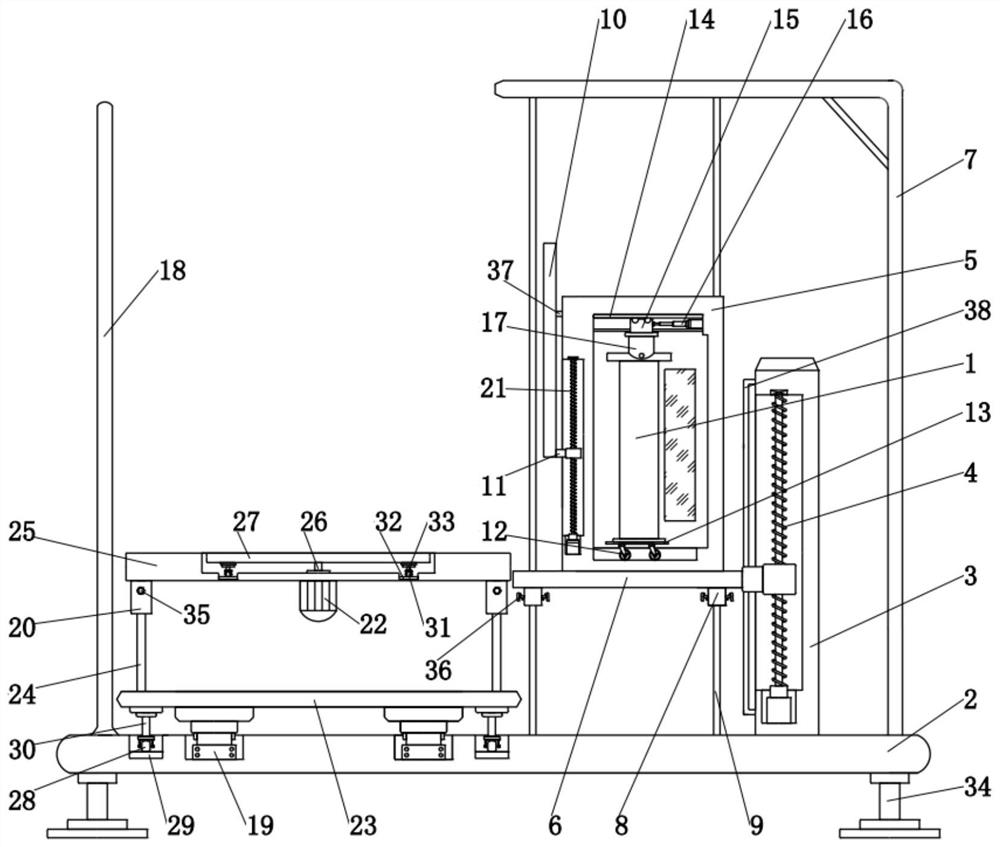
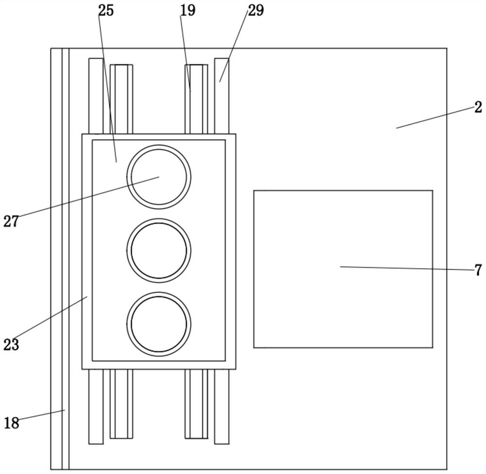
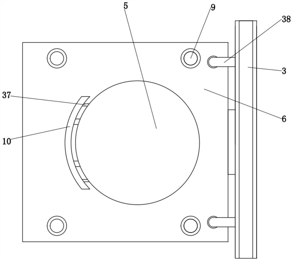
[0028] The present invention is specifically described below in conjunction with accompanying drawing, as Figure 1-7As shown, an X-ray flaw detection automatic verification device includes an X-ray flaw detector 1 and a rectangular base 2, the rectangular base 2 is provided with a lifting support structure, the X-ray flaw detector 1 is installed on the lifting support structure, and the lifting support structure A shielding structure for protecting the X-ray flaw detector 1 is provided on the top, and an object bearing structure is provided on the upper wall of the rectangular base 2 and located on the right side of the X-ray flaw detector 1; the lifting support structure includes: a support frame 3, a first screw module 4 And the storage box 5; the support frame 3 is installed on the upper wall of the rectangular base 2, and is close to the left end, the side wall of the support frame 3 is provided with a first bar-shaped groove, and the first lead screw module 4 is installed...


PUM


Abstract

The invention discloses an X-ray flaw detection automatic calibrating device which comprises an X-ray flaw detector and a rectangular base, a lifting supporting structure is arranged on the rectangular base. The X-ray flaw detector is mounted on the lifting supporting structure; a shielding structure for protecting the X-ray flaw detector is arranged on the lifting supporting structure; an articlebearing structure is arranged on the upper wall surface of the rectangular base and is positioned on the right side of the X-ray flaw detector. The invention has the following beneficial effects: thelifting supporting structure is convenient for the X-ray flaw detector to lift and adjust the use height; manual operation is not needed, time and labor are saved in operation, the shielding structure is adopted, the X-ray flaw detector is shielded and protected, the use of the X-ray flaw detector is not hindered, the X-ray flaw detector is exposed when in use and is protected when not in use, anarticle to be calibrated is placed and borne through the article bearing structure, and meanwhile, the use position can be adjusted, so that the calibration position can be conveniently adjusted whenthe article is detected.

Description

technical field [0001] The invention relates to the field of X-ray flaw detection, in particular to an automatic verification device for X-ray flaw detection. Background technique [0002] X-ray flaw detection refers to the use of X-rays to penetrate metal materials, and due to the different absorption and scattering effects of the materials on the rays, the film sensitivity is different, so images with different blackness are formed on the negative film, and the material is judged accordingly. A method of inspection for internal defect conditions. [0003] In order to ensure that the internal quality of metal material items is qualified, X-ray flaw detection methods will be used when performing internal inspections of metal material items. The traditional X-ray flaw detector has a single shape and structure. When in use, the position and height cannot be adjusted for support, and manual adjustment is required. And when the items are placed, it is necessary to adjust the us...

Claims


Application Information

Patent Timeline
Patent Type & Authority Applications(China)
IPC IPC(8): G01N23/04G01N23/18B25H1/12
CPCG01N23/04G01N23/18B25H1/12Y02E30/30
Inventor 吴鹤林吴迁
Owner 大冶市探伤机有限责任公司
Why Eureka
Try Eureka