System and method for dynamic photogrammetry based on X-ray machine detector
A dynamic photography, measurement system technology, applied in photogrammetry/videogrammetry, measurement devices, instruments for radiological diagnosis, etc.
- Summary
- Abstract
- Description
- Claims
- Application Information
AI Technical Summary
Problems solved by technology
Method used
Image

Examples
Embodiment 1
[0125] combined with figure 1 and 2 As shown, the dynamic photogrammetry system based on the X-ray machine detector provided in this embodiment is used to dynamically track and capture the actual position of the detector in real time in a static or moving state, so as to quickly align the actual position of the detector with the X-ray machine, Reach the preset transillumination state and obtain qualified X-ray films at one time, including:
[0126] An X-ray machine for emitting X-rays to illuminate the target object and a detector for detecting and imaging the X-rays absorbed by the target object from the X-ray machine;
[0127] Marking points 1, 2, 3, and 4 are sequentially set on the detector near the four corners, any one of the marking points is marked with decoding information for unique identification, and a marking line is set between two adjacent marking points, and A first attitude sensor built into the detector for collecting the attitude information of the detecto...
Embodiment 2
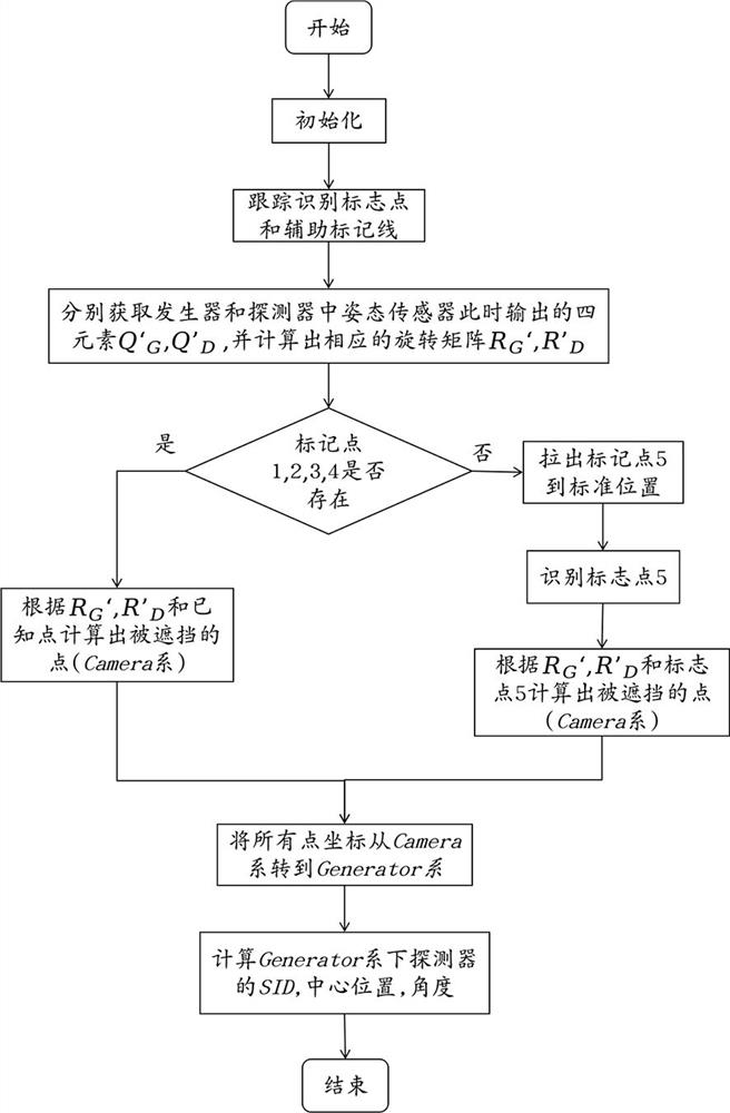
[0137] In order to make full use of the dynamic photogrammetry positioning system provided in Embodiment 1, this embodiment will describe in detail the steps specifically included in the dynamic photogrammetry method based on the X-ray machine detector provided by the dynamic photogrammetry positioning system. Combined with the manual image 3 Instructions include the following steps:
[0138] Step ST100, the X-ray machine is installed in place, the detector is placed in the effective transillumination range of the X-ray machine and any mark point 1, 2, 3, 4 on the detector can be captured by the binocular camera unit on the X-ray machine , identify, and complete the coordinate initialization, establish a world coordinate system centered on the binocular camera unit, which is recorded as the Camera system, specifically as Figure 9 shown;
[0139] Step ST200, move the X-ray machine and / or the detector so that the detector and the target object enter the transillumination ran...
Embodiment 3
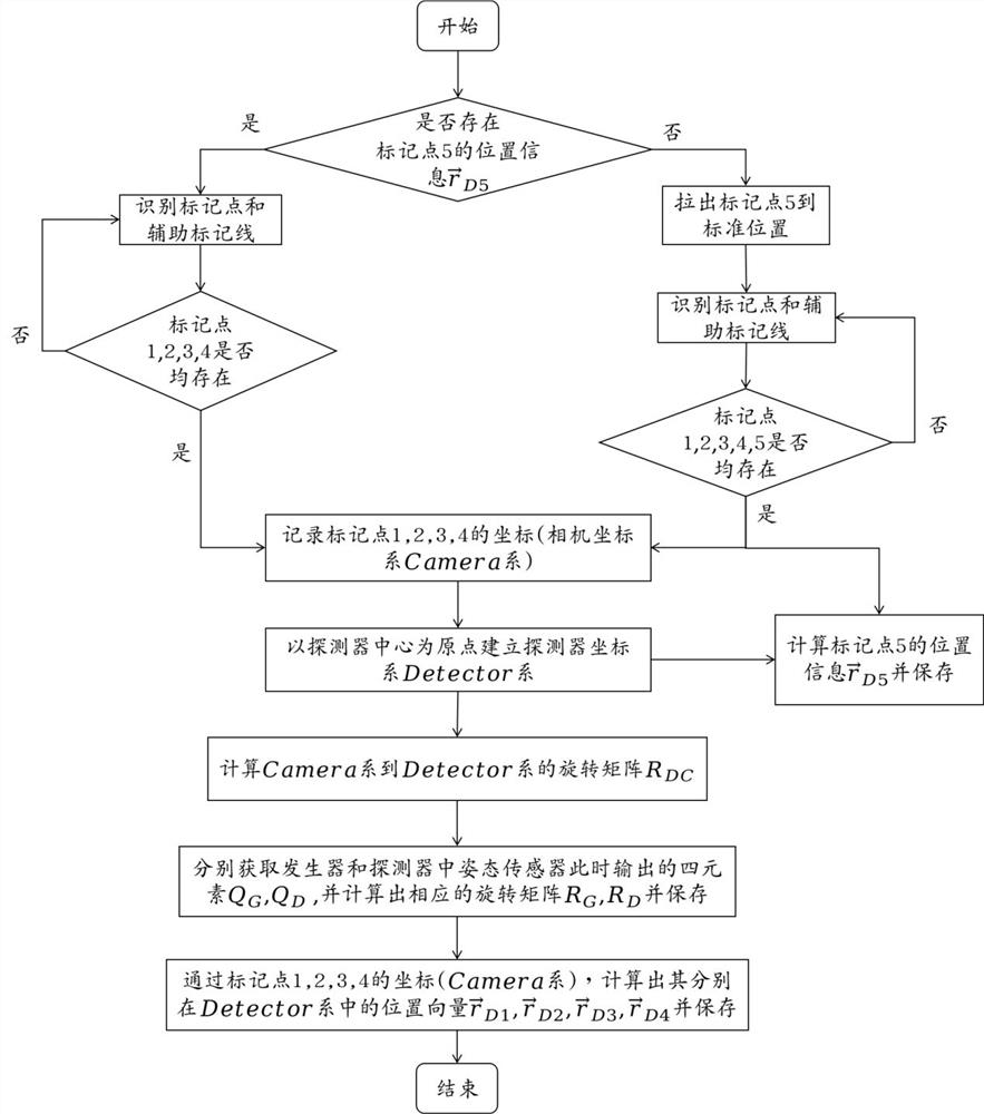
[0146] This embodiment specifically provides an optimal method that can satisfy the coordinate initialization mentioned in step ST100 in Embodiment 2, combined with the Figure 4 Shown, specifically through the following methods:
[0147] Step ST110, judging whether there is position information of the marker point 5 , if it exists, execute step ST130, if not, execute step ST120;
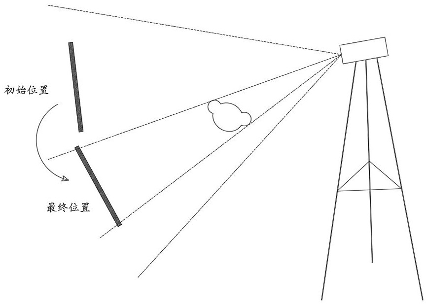
[0148] Step ST120, pull out the auxiliary positioning bar in the detector to the calibration position, the binocular camera unit captures and recognizes the marking points 1, 2, 3, 4 and the marking line, and judges whether the marking points 1, 2, 3, 4 are all Recognize, if all have been recognized, then execute step ST140; if not recognized or partially recognized, then adjust the position of the detector, repeat this step until all are recognized, and save the position information of the marker point 5 ;
[0149] Step ST130, identify marking points 1, 2, 3, 4 and marking lines, and judge whe...
PUM
 Abstract
Description
Claims
Application Information