
Three-dimensional dynamic measurement device and method based on linear array area array

A measuring device and three-dimensional dynamic technology, which is applied in the direction of measuring devices, optical devices, instruments, etc., can solve the problem that high-frequency dynamic measurement is difficult to take into account, and achieve the effect of low production cost and reduced data volume.

Pending Publication Date: 2021-04-27
AVIC BEIJING CHANGCHENG AVIATION MEASUREMENT & CONTROL TECH INST +2
View PDF6 Cites 2 Cited by
  • Summary
  • Abstract
  • Description
  • Claims
  • Application Information

AI Technical Summary

Problems solved by technology

[0004] Purpose of the present invention: In response to the demand for high-precision and high-frequency dynamic photogrammetry in practical applications, the present invention is dedicated to solving the problem that it is difficult to balance high-precision and high-frequency dynamic measurement at high sampling frame rates in photogrammetry, and can provide high-precision, high-frequency High-frequency dynamic three-dimensional measurement capability

Method used


Image

  • Three-dimensional dynamic measurement device and method based on linear array area array
  • Three-dimensional dynamic measurement device and method based on linear array area array
  • Three-dimensional dynamic measurement device and method based on linear array area array

Examples


Embodiment 1

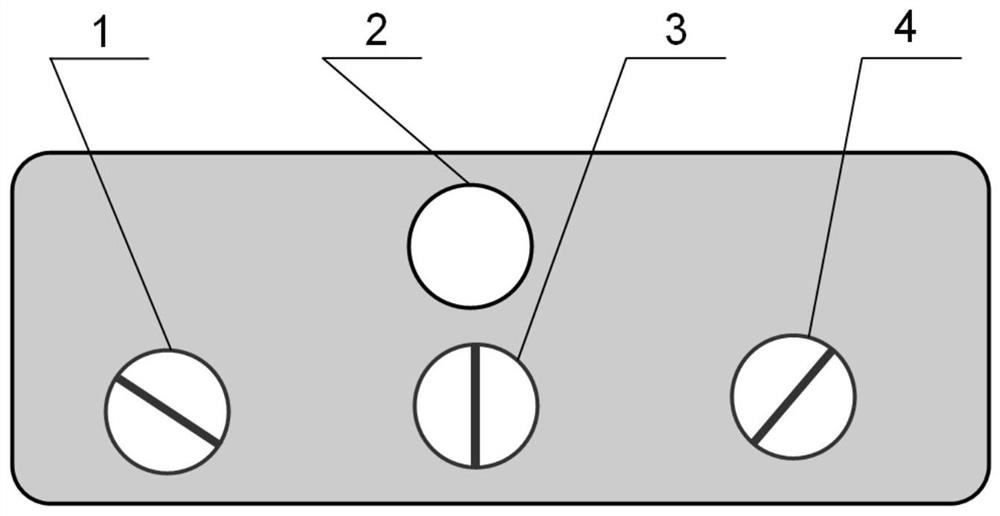
[0013] A low-resolution area-scan camera with an objective lens is used to acquire a two-dimensional image of the area under test. In a two-dimensional image, the target of the measured area is imaged in the two-dimensional image. These targets can be detected to obtain the position of the target in the image coordinate system. It is also possible to use multiple area array cameras to cover the measured area, and use the corresponding relationship of the targets in the two-dimensional image to calculate the low-precision three-dimensional coordinates.

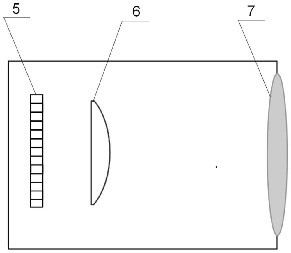
[0014] Such as figure 2 As shown, a cylindrical lens 6 is installed between the line sensor 5 and the objective lens 7 of the line camera to compress the scene in the measured area into a one-dimensional image. When the resolution of the line array camera is high, the data acquisition and transmission pressure is relatively small.

[0015] After the objective lens images the area to be measured, a two-dimensional imaging su...

Embodiment 2

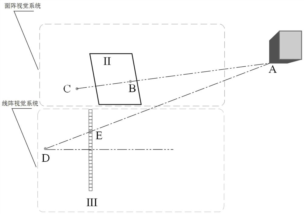
[0025] This embodiment provides a three-dimensional dynamic measurement method based on a line array and an area array, using the measurement device as described in Embodiment 1, specifically including the following steps:

[0026] Step 1: adopt at least one area array camera to obtain the two-dimensional image of the measured target;

[0027] Step 2: Target detection in the 2D image containing the object under test:

[0028] Step 3: Each line camera in the line array vision system obtains a frame of one-dimensional image respectively: according to the target detection result in the two-dimensional image and the relative geometric relationship between the line array camera and the area array camera, determine the The projection coordinates of the three-dimensional space target corresponding to the target in the one-dimensional image acquired by the line array camera, so as to determine the corresponding relationship between the target in the two-dimensional image and the targe...


PUM


Abstract

The invention relates to a three-dimensional dynamic measurement device and a three-dimensional dynamic measurement method based on a linear array area array, belongs to the field of visual dynamic photogrammetry, and particularly relates to a measurement device and a measurement method of an area array vision system and a linear array vision system. According to the invention, the three-dimensional coordinates of the target are calculated on the basis of the corresponding relationship between the target in the image obtained by the area array camera and the target in the image obtained by the linear array camera, and the corresponding relationship between the targets in the images obtained by the different linear array cameras.

Description

technical field [0001] The invention belongs to the field of visual dynamic photogrammetry, and relates to a measuring device and a measuring method of an area array vision system and a line array vision system, in particular to a corresponding relationship between a target in an image obtained by an area array camera and a target in an image obtained by a line array camera, and The corresponding relationship of the target in the image is obtained by different line array cameras obtained by calculation, and the three-dimensional coordinates of the target are calculated accordingly. Background technique [0002] The dynamic measurement of the three-dimensional coordinates of the object space can be applied in many fields. The dynamic measurement of the three-dimensional coordinates of the object can be obtained based on the stereo vision of multiple area array cameras, or based on the stereo vision of multiple line array cameras, or through other contact sensors. Compared wi...

Claims


Application Information

Patent Timeline
Patent Type & Authority Applications(China)
IPC IPC(8): G01B11/00
CPCG01B11/005
Inventor 王君秋
Owner AVIC BEIJING CHANGCHENG AVIATION MEASUREMENT & CONTROL TECH INST
Learn More