
Anti-falling switch cabinet capable of being opened in four directions

A switchgear, anti-drop technology, applied in the field of switchgear, can solve problems such as reduced production efficiency, delay in construction period, electrical failure, etc.

Inactive Publication Date: 2020-12-01
武汉市晶博特科技有限公司
View PDF0 Cites 3 Cited by
  • Summary
  • Abstract
  • Description
  • Claims
  • Application Information

AI Technical Summary

Problems solved by technology

[0003] In some factories, workshops and other places, the power switch is often placed in the switch cabinet; the switch cabinet is composed of a cabinet body, a cabinet door and internal electrical components; different switch cabinets need to flexibly adjust the opening method of the cabinet door according to different installation spaces, as above Open, open down, open left or right; according to the space of the installation site, determine the opening position of the cabinet door. When the switch cabinet is customized, install the cabinet door to the required opening position. It will reduce the production efficiency; in addition, during the installation of the switchgear, the readjustment of the cabinet door will occur due to various factors, which will inevitably cause delays in the construction period for the manufacturer or the user, that is, the cabinet door cannot be easily installed on the switchgear during installation.
[0004] For the switchgear hanging on the wall, it is unavoidable that the switchgear and the wall are not firm, and after a long time of use, it will fall, and the wire will be broken when it falls, causing electrical failure, or causing a short-circuit fire

Method used


Image

  • Anti-falling switch cabinet capable of being opened in four directions
  • Anti-falling switch cabinet capable of being opened in four directions
  • Anti-falling switch cabinet capable of being opened in four directions

Examples


Embodiment Construction

[0043] The specific implementation manners of the present invention will be further described in detail below in conjunction with the accompanying drawings and embodiments. The following examples or drawings are used to illustrate the present invention, but not to limit the scope of the present invention.

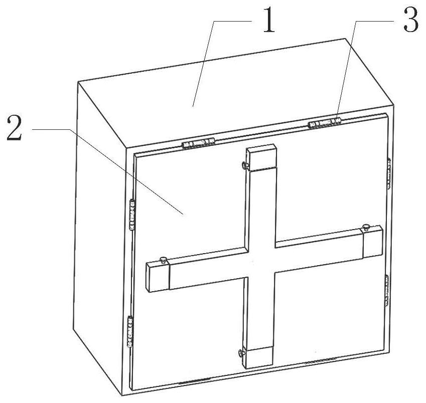
[0044] Such as image 3 As shown, it includes cabinet body 1 and cabinet door 2, among which Figure 5 As shown, the cabinet door 2 is installed on the cabinet body 1, which is characterized in that: as Figure 4 , 6 As shown, two hinge mechanisms 3 are respectively installed on the four sides of the cabinet door 2; the eight hinge mechanisms 3 installed on the four sides of the cabinet door 2 are all connected to the cabinet body 1 by bolts.

[0045] In the present invention, the cabinet door 2 is installed on the cabinet body 1 through the eight hinge mechanisms 3 designed, and the opening of the hinge mechanism 3 in the corresponding orientation can be controlled by t...


PUM


Abstract

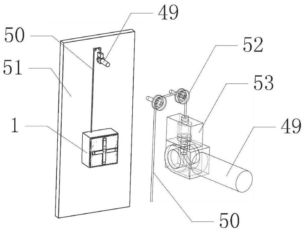
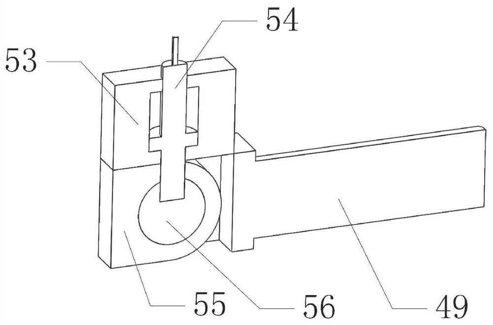
The invention belongs to the technical field of switch cabinets, and particularly relates to an anti-falling switch cabinet capable of being opened in four directions. The switch cabinet comprises a cabinet body and a cabinet door, and after one side of the door is opened, if a person presses a pressing rod on the other side, the cabinet door can be detached; in order to prevent the situation, anadjusting mechanism is designed to prevent the situation that people for saving trouble completely detach but not install the cabinet door, and the detaching difficulty of the cabinet door is increased through the designed adjusting mechanism. According to the invention, a wire winding rod is designed to prevent the wires in the switch cabinet from being snapped after being subjected to downward pulling force of the cabinet body after the switch cabinet is used for a long time or installed loosely and falls off, so that electrical faults or short-circuit fire disasters are avoided; and after the cabinet body falls off, the cabinet body pulls the insertion rod through the pull rope, so that the insertion rod moves upwards to lose swing limitation between the wire winding rod and the fixed support lug, the wire winding rod can swing downwards, the electric wire wound on the wire winding rod falls off through a lower plate, and the defect that the length of the falling electric wire of the switch cabinet is not enough is overcome.

Description

[0001] Technical field [0002] The invention belongs to the technical field of switch cabinets, in particular to a four-way openable anti-drop switch cabinet. Background technique [0003] In some factories, workshops and other places, the power switch is often placed in the switch cabinet; the switch cabinet is composed of a cabinet body, a cabinet door and internal electrical components; different switch cabinets need to flexibly adjust the opening method of the cabinet door according to different installation spaces, as above Open, open down, open left or right; according to the space of the installation site, determine the opening position of the cabinet door. When the switch cabinet is customized, install the cabinet door to the required opening position. It will reduce the production efficiency; in addition, when the switchgear is installed, the cabinet door will be readjusted due to various factors, which will inevitably cause delays in the construction period for the ...

Claims


Application Information

Patent Timeline
IPC IPC(8): H02B1/38H02B1/30H02B1/052H02B1/40
CPCH02B1/052H02B1/30H02B1/38H02B1/40
Inventor 不公告发明人
Owner 武汉市晶博特科技有限公司
Learn More