
Wiring groove concrete backfilling equipment for building decoration

A wiring trough and concrete technology, applied in the field of wiring trough concrete backfilling equipment, can solve the problems of low work efficiency, difficulty in controlling concrete voids, cumbersome operation steps, etc., and achieve the effects of increasing backfilling speed, reducing voids, and simplifying working steps.

Active Publication Date: 2020-12-08
安徽新城建设有限公司
View PDF4 Cites 1 Cited by
  • Summary
  • Abstract
  • Description
  • Claims
  • Application Information

AI Technical Summary

Problems solved by technology

[0004] In order to overcome the shortcomings of cumbersome operation steps, low work efficiency, and difficulty in controlling the gaps between concrete when backfilling wiring channels with concrete, the technical problem of the present invention is to provide a method that can simplify concrete backfill steps and improve work efficiency. Concrete backfilling equipment for wiring grooves used in building decoration to vibrate the backfilled concrete to reduce its voids

Method used


Image

  • Wiring groove concrete backfilling equipment for building decoration
  • Wiring groove concrete backfilling equipment for building decoration
  • Wiring groove concrete backfilling equipment for building decoration

Examples


Embodiment 1

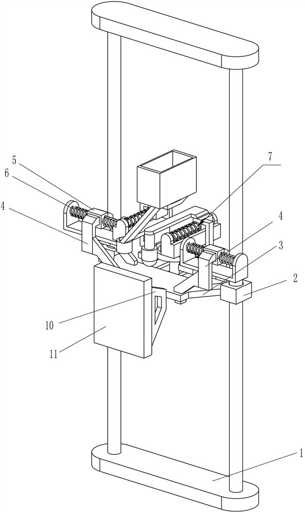
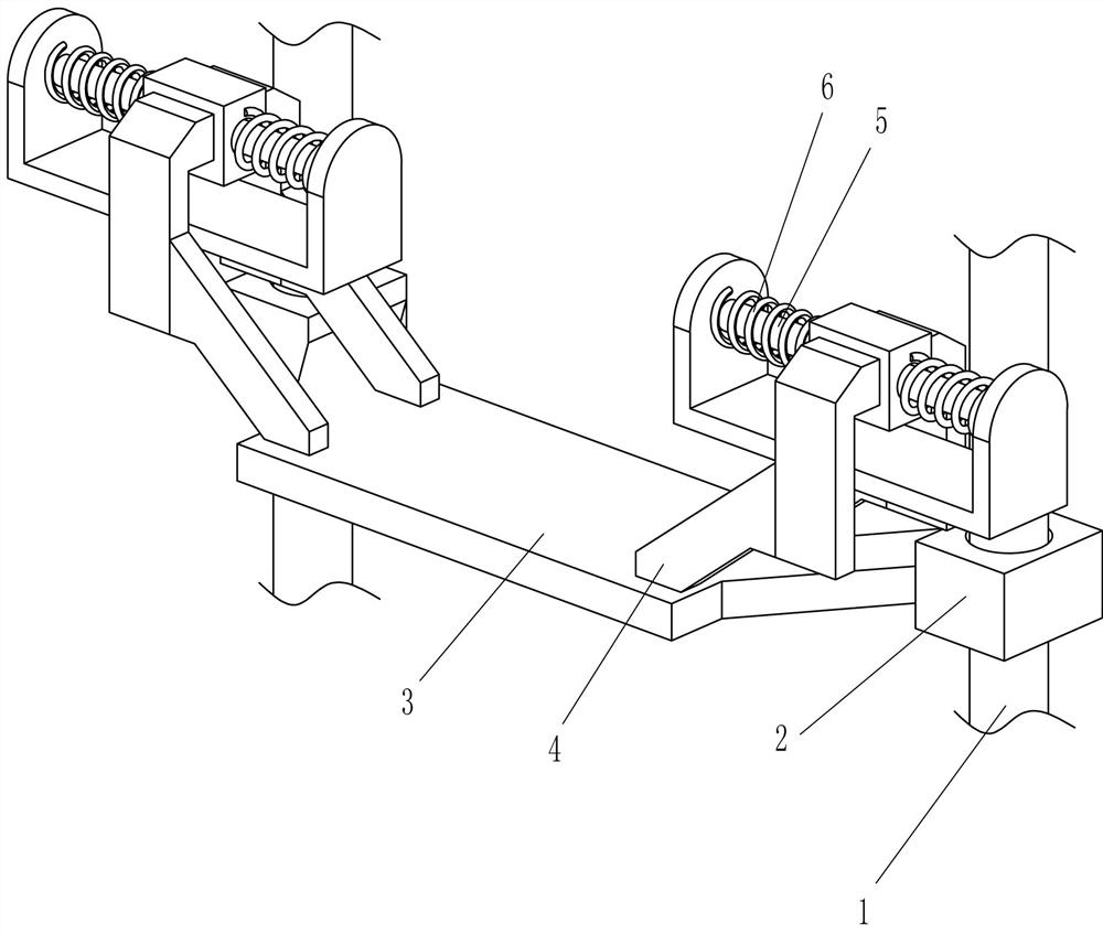
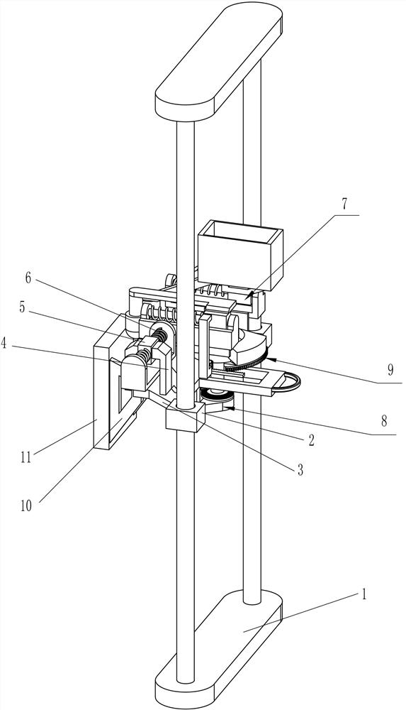
[0025] A wiring trench concrete backfill equipment for building decoration, such as Figure 1-4 As shown, it includes a mounting frame 1, a first moving pair 2, a fixed frame 3, a connecting block 4, a second moving pair 5, a first elastic member 6, a feeding device 7 and a driving device 8, specifically:

[0026] Mounting frame 1 quantity is two groups, is connected with two groups of first mobile pair 2 between mounting frame 1, is connected with fixed frame 3 between the mobile parts of first mobile pair 2, and fixed frame 3 upper side front and rear sides are all connected with The connecting block 4 is connected with the second mobile pair 5, the second mobile pair 5 is connected with the first elastic member 6, and the moving parts of the second mobile pair 5 are provided with a feeding device 7 and a fixed frame 3 The right side is provided with a driving device 8, and the driving device 8 cooperates with the feeding device 7.

[0027] When it is necessary to backfill ...

Embodiment 2

[0029] On the basis of Example 1, such as Figure 5-7 As shown, the feeding device 7 includes a third moving pair 71, a second elastic member 72, an extension rod 73, a vibration block 74, a concrete box 75 and an electric control valve 76, specifically:

[0030] The inner side of the moving part of the second moving pair 5 is connected with the third moving pair 71, the third moving pair 71 is connected to each other, the third moving pair 71 is connected with the second elastic member 72, the movement of the third moving pair 71 on the front side Part upper side is connected with extension rod 73, and extension rod 73 left side is connected with shock block 74, is connected with concrete box 75 on the mobile part of rear side the 3rd moving pair 71, and concrete box 75 lower left side is connected with electric control valve 76.

[0031] When the driving device 8 is working, the driving device 8 will first contact the third moving pair 71 on the front side, and the driving d...


PUM


Abstract

The invention relates to building decoration equipment, in particular to wiring groove concrete backfilling equipment for building decoration. According to the equipment, concrete backfilling steps can be simplified, the working efficiency can be improved, backfilled concrete is vibrated to decrease gaps of the backfilled concrete. The wiring groove concrete backfilling equipment for building decoration comprises two sets of mounting frames; a first moving pair is arranged between the mounting frames; and a fixing frame is arranged on a moving part of the first moving pair. By adopting a modethat concrete is placed in a concrete box and flows into a wiring groove through an electric control valve, and a mode that a vibration block vibrates the backfilled concrete, so that the backfillingprocess of the concrete can be conducted without manually holding a cement shovel, the backfilling speed can be increased, and manpower is saved.

Description

technical field [0001] The invention relates to building decoration equipment, in particular to a concrete backfilling equipment for wiring grooves used for building decoration. Background technique [0002] When burying hidden wires in a building, it is necessary to excavate wiring grooves on the wall, and lay hidden wires in the wiring grooves. After laying and inspecting hidden wires, it is necessary to backfill the wiring grooves. Currently, the wiring grooves are backfilled. The methods are all using the traditional concrete construction method, that is, it is necessary to manually hold a variety of cement shovels to scoop up the cement, and wipe it in the wiring groove, fill the wiring groove, and then smooth it, but using such There are many problems in this method. Not only does it require frequent shoveling and smoothing manually, but also the gap between the concrete is too large, and it is difficult to control the gap with the traditional method, which leads to po...

Claims


Application Information

Patent Timeline
IPC IPC(8): E04G21/04E04G21/06
CPCE04G21/04E04G21/063
Inventor 李景乔
Owner 安徽新城建设有限公司
Learn More