Mechanical equipment lubricating device

A technology for lubricating devices and mechanical equipment, applied in the direction of mechanical equipment, engine lubrication, lubricating parts, etc., can solve the problem of single way of lubricating oil application, and achieve the effect of diversified oiling methods, convenient and efficient oiling

Inactive Publication Date: 2020-12-15
陈思涵
View PDF1 Cites 2 Cited by
  • Summary
  • Abstract
  • Description
  • Claims
  • Application Information

AI Technical Summary

Problems solved by technology

[0003] In the Chinese utility model patent document with the publication number CN208397671U, a lubricating device for mechanical equipment is disclosed. The device can clean the residual dirt inside the workpiece through the cleaning device. Oil lubrication is sufficient, and the mobile device facilitates the frame to drive the lubricating mechanism and the cleaning device to move, but the method of applying the lubricating oil to the device is too simple, and there are many restrictions and inconveniences in use

Method used


Image

  • Mechanical equipment lubricating device
  • Mechanical equipment lubricating device
  • Mechanical equipment lubricating device

Examples


Embodiment 1

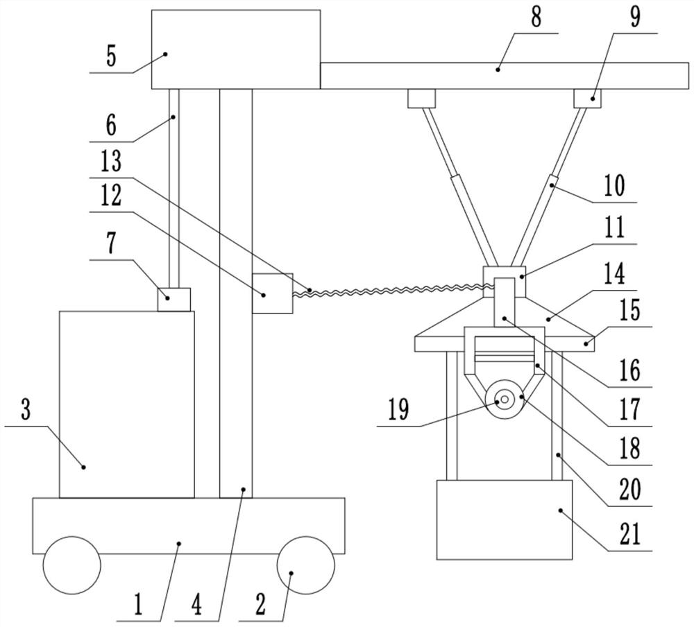
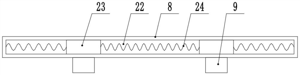
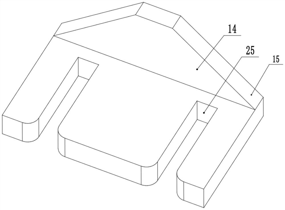
[0022] see Figure 1-4 , a lubricating device for mechanical equipment, comprising a base 1, the four corners of the bottom of the base 1 are provided with moving wheels 2, the top of the base 1 is fixedly connected to a lubricating oil tank 3, the top of the base 1 is fixedly connected to a column 4, and the top of the column 4 is fixedly connected to The transfer box 5 and the top of the lubricating oil tank 3 are fixedly connected to the delivery pump 7, the output end of the delivery pump 7 is fixedly connected to the delivery pipe 6, the delivery pipe 6 is fixedly connected to the transfer box 5, and one end of the transfer box 5 is fixedly connected to the cross bar 8 Cross bar 8 A follow-up buffer adjustment mechanism is provided inside, and the follow-up buffer adjustment mechanism connects two first telescopic rods 10, the bottom end of the first telescopic rod 10 is connected to the first connecting seat 11 in rotation, and the bottom end of the first connection is fi...

Embodiment 2

[0028] see Figure 1-4 , a lubricating device for mechanical equipment, comprising a base 1, the four corners of the bottom of the base 1 are provided with moving wheels 2, the top of the base 1 is fixedly connected to a lubricating oil tank 3, the top of the base 1 is fixedly connected to a column 4, and the top of the column 4 is fixedly connected to The transfer box 5 and the top of the lubricating oil tank 3 are fixedly connected to the delivery pump 7, the output end of the delivery pump 7 is fixedly connected to the delivery pipe 6, the delivery pipe 6 is fixedly connected to the transfer box 5, and one end of the transfer box 5 is fixedly connected to the cross bar 8 Cross bar 8 A follow-up buffer adjustment mechanism is provided inside, and the follow-up buffer adjustment mechanism connects two first telescopic rods 10, the bottom end of the first telescopic rod 10 is connected to the first connecting seat 11 in rotation, and the bottom end of the first connection is fi...


PUM


Abstract

The invention discloses a mechanical equipment lubricating device, and relates to the technical field of mechanical lubrication. The mechanical equipment lubricating device comprises a base, wherein moving wheels are arranged at four corners of the bottom end of the base; a lubricating oil tank is fixedly connected to the top of the base; a first connecting seat is rotationally connected to the bottom ends of first telescopic rods; a first fixed plate is fixedly connected to the bottom end of the first connecting seat; a second fixed plate is fixedly connected to the bottom end of the first fixed plate; a second connecting seat is fixedly connected to the side edge of the middle of a stand column; a hanging frame is arranged on the second fixed plate; a connector is fixedly connected to the bottom end of the hanging frame; a smearing device is fixedly arranged on the connector; a handheld pipe is fixedly connected to the top end of the hanging frame; and a spring pipe is fixedly connected between the handheld pipe and the second connecting seat. Through arrangement of a transfer box, low-speed natural escape of lubricating oil can be achieved, and smearing work is facilitated; through arrangement of a follow-up buffer adjusting mechanism, the oiling position can be controlled conveniently and stably; and in addition, the smearing device can be independently taken out for oilingoperation, oiling modes are diversified, and oiling is convenient and efficient.

Description

technical field [0001] The invention relates to the technical field of mechanical lubrication, in particular to a mechanical equipment lubrication device. Background technique [0002] At present, with the continuous development of my country's economy, the construction progress of the machinery industry is advancing by leaps and bounds, and the demand for machinery and equipment is increasing. In the process of operation and use of machinery and equipment, the role of lubricating oil is indispensable. Lubricating oil is a liquid or semi-solid lubricant used in various types of automobiles and mechanical equipment to reduce friction and protect machinery and processed parts. It mainly plays the roles of lubrication, auxiliary cooling, rust prevention, cleaning, sealing and buffering. As long as it is applied between two relatively moving objects and can reduce the friction and wear of the two objects due to the function of contact, it is a lubricating oil. [0003] In the C...

Claims


Application Information

Patent Timeline
Patent Type & Authority Applications(China)
IPC IPC(8): F16N7/38F16N7/24F16N21/00F16N31/02
CPCF16N7/24F16N7/38F16N21/00F16N31/02
Inventor 李桦濛
Owner 陈思涵
Why Eureka
Try Eureka