Method and apparatus for controlling combustion in oxygen fired boiler

a technology of combustion control and oxygen fired boiler, which is applied in the direction of combustion types, furnaces, steam generation using hot heat carriers, etc., can solve the problems of low efficiency and inpractical use, and achieve the effects of improving efficiency, improving efficiency and improving efficiency

Active Publication Date: 2009-11-05
ELECTRIC POWER DEVELOPMENT COMPANY +1
View PDF12 Cites 41 Cited by
  • Summary
  • Abstract
  • Description
  • Claims
  • Application Information

AI Technical Summary

Benefits of technology

[0023]A method and an apparatus for controlling combustion in an oxygen fired boiler according to the invention, which set an amount of oxygen supplied to a boiler body in response to boiler load demand and detect the heat absorption of the boiler body to control the recirculation flow rate of all the gas guided to the boiler body such that the heat absorption of the boiler body becomes equal to the targeted heat absorption so as to control oxygen concentration of all the gas guided to the boiler body, so that the amount of oxygen supplied to the boiler body even including oxygen included in the recirculation gas. Thus, excellent effects and advantages can be obtained such that combustion control of boiler body is much simplified and stabilized, and thus easily applicable to an existing air fired boiler for stabilization of the combustion.

Problems solved by technology

However, any of them has lower efficiency and is not in practical use.
However, oxygen combustion involves a technical problem of higher flame temperature to be dealt with, for example, by improving heat resistance and lifespan of materials of a combustion furnace.

Method used


Image

  • Method and apparatus for controlling combustion in oxygen fired boiler
  • Method and apparatus for controlling combustion in oxygen fired boiler
  • Method and apparatus for controlling combustion in oxygen fired boiler

Examples


Embodiment Construction

[0053]Next, an embodiment of the invention will be described in conjunction with the attached drawings.

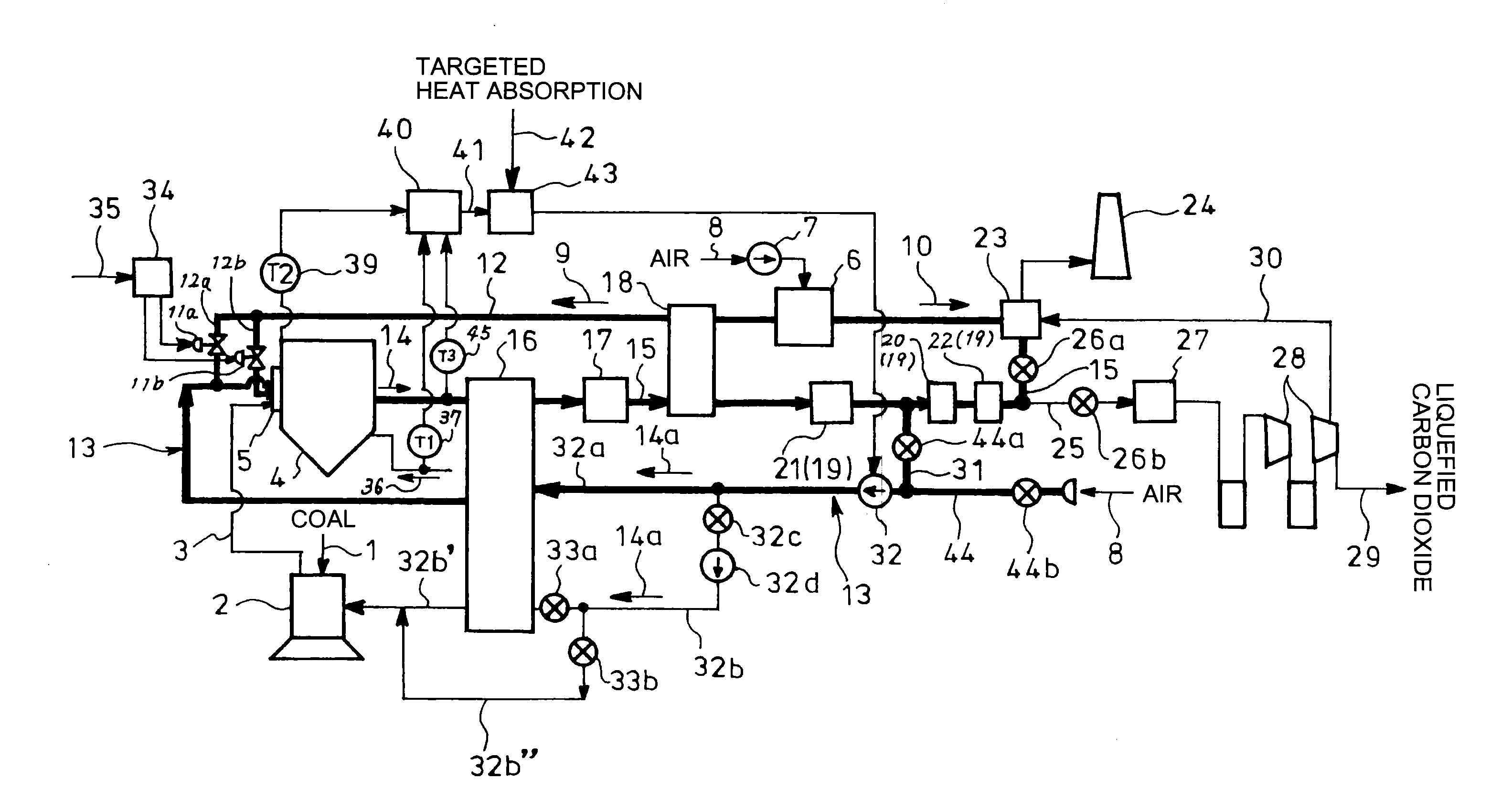
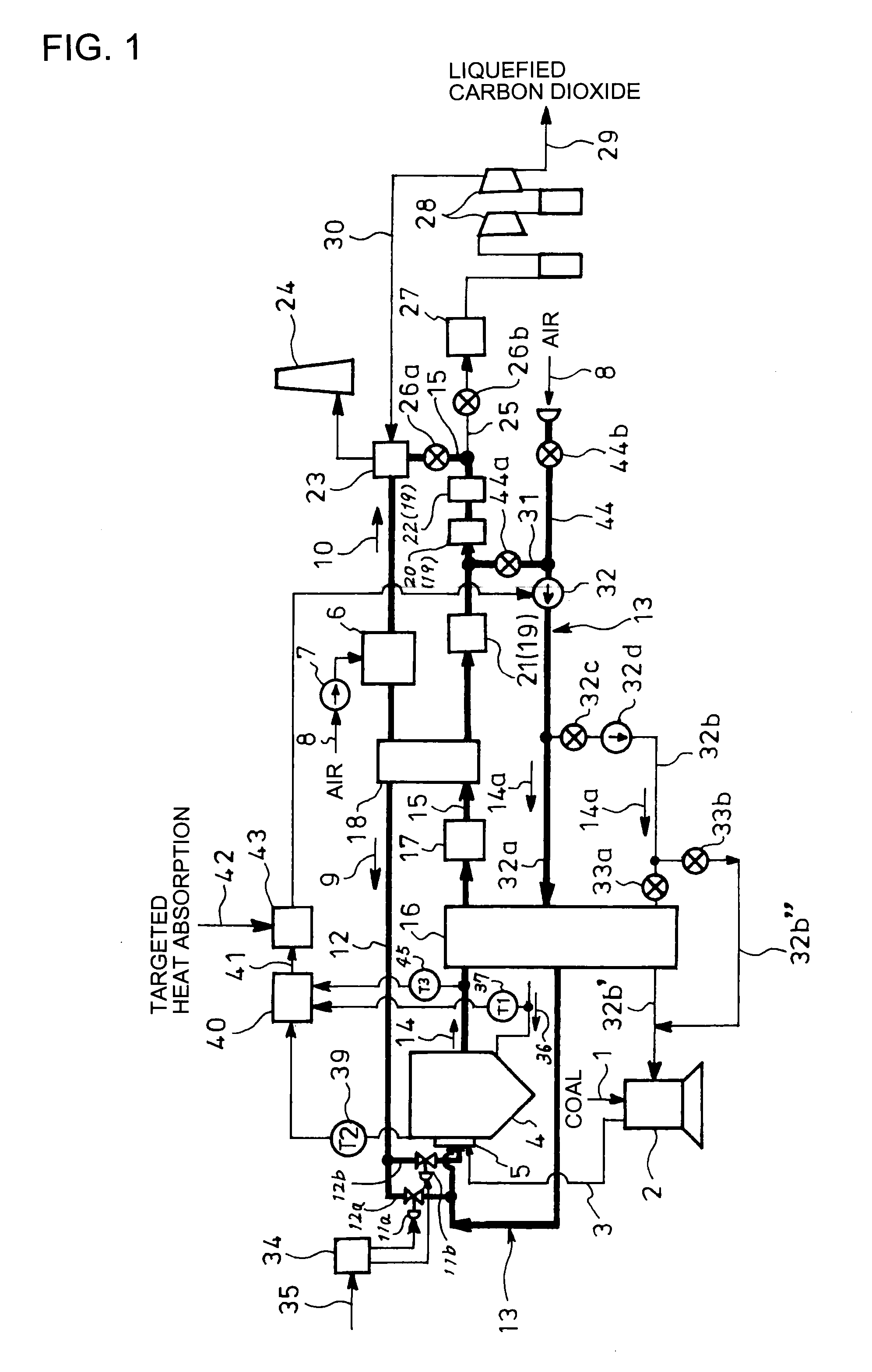
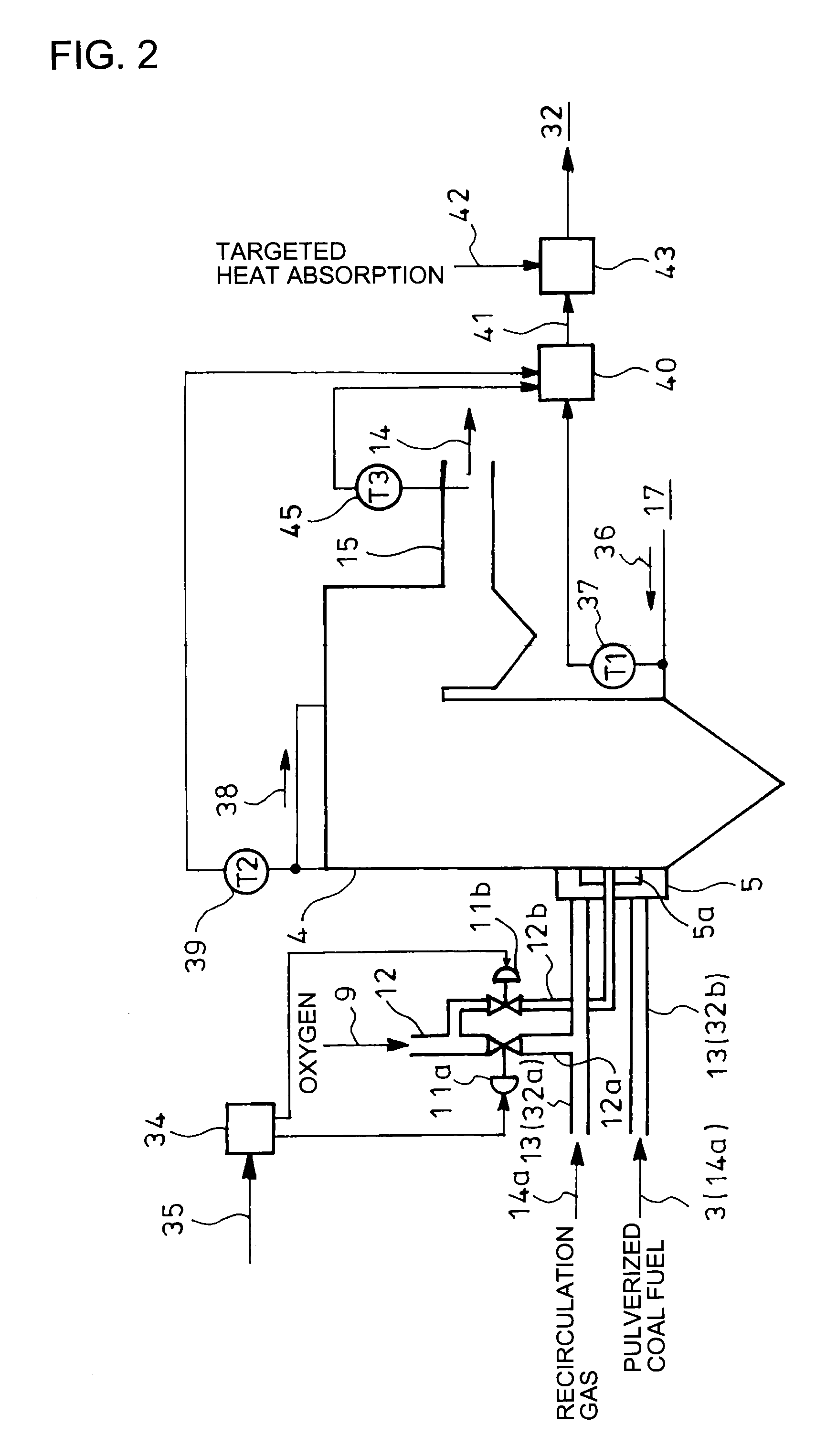
[0054]FIG. 1 is a block diagram showing an embodiment of an oxygen fired boiler according to the invention applied to a coal fired boiler. Coal 1 as fuel is pulverized in a coal mill 2 as fuel supply means into pulverized coal fuel 3 which is supplied to a burner 5a in a wind box 5 on a boiler body or furnace 4 shown in FIG. 2. Air 8 is supplied via a blower 7 to an air separation unit 6 where air 8 is separated into oxygen 9 and the other nitrogen-prevailing gas 10. The oxygen 9 separated by the air separation unit 6 and passed through an oxygen supply flow passage 12 is partly supplied via a line 12a to an exhaust gas recirculation flow passage 13 detailed hereinafter and then supplied as gas mixed with recirculation gas 14a to the wind box 5, the remainder being directly supplied via a line 12b to the burner 5a.

[0055]In the boiler body 4, the pulverized coal fuel 3 is burned wi...


PUM


Abstract

Provided are a method and an apparatus for controlling combustion in an oxygen fired boiler which are easily applicable to an existing air fired boiler for easy and stable control of the combustion.Oxygen with a setting amount in accordance with a boiler load demand 35 is supplied to a boiler body 4. Heat absorption amount of the boiler is measured from inlet temperature of feedwater supplied to the boiler body 4 and outlet temperature of steam. Recirculation flow rate of combustion exhaust gas 14a is controlled such that heat absorption amount 41 of the boiler body 4 becomes equal to a targeted heat absorption amount 42 to thereby control oxygen concentration in all gas guided to the boiler body 4.

Description

TECHNICAL FIELD[0001]The present invention relates to a method and an apparatus for controlling combustion in an oxygen fired boiler, and especially relates to a method and an apparatus for controlling combustion in an oxygen fired boiler when oxygen combustion is conducted using an existing air fired boiler.BACKGROUND ART[0002]Recently, global warming has been played up as environment-related issue on a mass global scale. It has been revealed that increase in concentration of carbon dioxide (CO2) in the atmosphere is one of main causes of the global warming, and thermal power plants are attracting attention as fixed sources of discharging the matter. Used as fuel for thermal power generation is petroleum, natural gas or coal. Especially coal, which has great mineable reserves, is expected to have increasing demand in the future.[0003]Coal has much carbon content in comparison with natural gas and petroleum and includes components such as hydrogen, nitrogen, sulfur and ash as inorga...

Claims


Application Information

Patent Timeline
Patent Type & Authority Applications(United States)
IPC IPC(8): F23N3/00F23L7/00F23N5/00F23C9/08F23B80/02
CPCF22B35/002F22B1/22F23C2202/30F23C2202/50F23C2900/99006F23J2900/15061F23L7/007F23N1/082F23N5/102F23N2021/12F23N2025/18F23N2025/19F23N2037/26F23N2041/10Y02E20/344F22B1/18F23C9/00F23N2221/12F23N2225/18F23N2225/19F23N2237/26F23N2241/10Y02E20/34F22B35/00F23C99/00F23N5/00
Inventor YAMADA, TOSHIHIKOFUJIMORI, TOSHIROTAKANO, SHINICHI
Owner ELECTRIC POWER DEVELOPMENT COMPANY
Why Eureka
Try Eureka