

3D holographic imaging device
A holographic image and projection surface technology, applied in the field of 3D images, can solve the problems of inconvenient handling, high manpower cost, and low efficiency of projection booths, and achieve the effects of easy storage and portability, guaranteed projection effect, and easy storage
- Summary
- Abstract
- Description
- Claims
- Application Information
AI Technical Summary
Problems solved by technology
Method used
Image

Examples
Embodiment 1
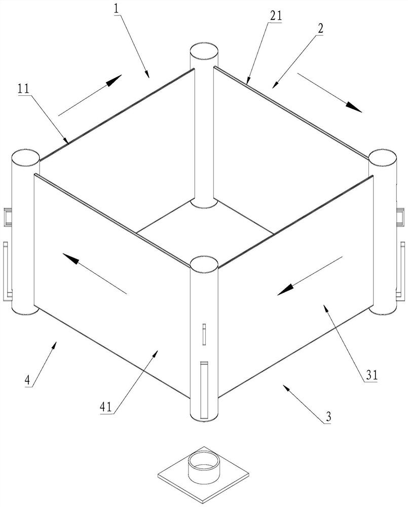
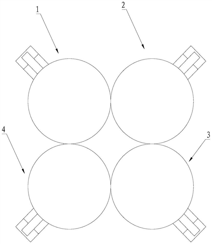
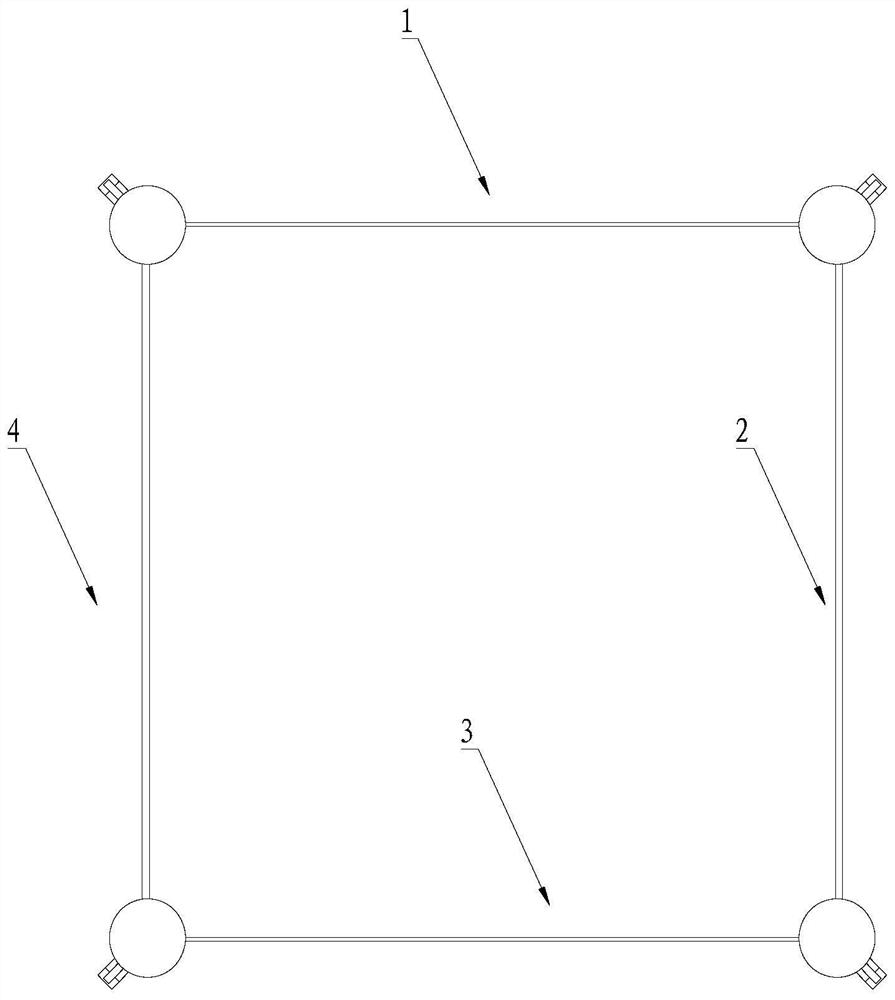
[0065] refer to Figure 1-Figure 4 , a 3D holographic image device, comprising a first projection assembly 1, a second projection assembly 2, a third projection assembly 3, and a fourth projection assembly 4; the first projection assembly 1, the second projection assembly 2, and the third projection assembly 3 and the fourth projection assembly 4 are sequentially telescopically connected; when the projection surface 11 of the first projection assembly, the projection surface 21 of the second projection assembly, the projection surface 31 of the third projection assembly and the projection surface 41 of the fourth projection assembly are expanded, The first projection assembly 1, the second projection assembly 2, the third projection assembly 3 and the fourth projection assembly 4 form a tetrahedron that communicates up and down; the top of the projection surface 11 of the first projection assembly is also provided with a light assembly, and the third projection assembly The pr...
Embodiment 2
[0067] refer to Figure 1-Figure 10 , the first projection assembly 1 includes a first screen 12 and a first winder 13; one end of the first screen 12 is connected to the fixed end of the fourth projection assembly 4, and the other end of the first screen 12 can be accommodated in the second screen by winding. Inside a winder 13.
[0068] refer to Figure 5 , the first winder 13 includes a housing 131, a reel 132 and a sliding assembly 133; the reel 132 is connected to the first curtain 12 through a clockwork spring; the upper and lower ends of the housing 131 are respectively provided with an upper support platform 134 and a lower support Platform 135; the two ends of the reel 132 are rotatably inserted in the axis centers of the upper support platform 134 and the lower support platform 135 through a rotating shaft 136 respectively; When the second anti-slip part 138 is on the top, the reel 132 is limited; the lower support platform 135 is provided with a longitudinally arr...
Embodiment 3
[0074] The difference between this embodiment and the second embodiment is that simultaneous projection on four sides can be realized.
[0075] Preferably, the projection surface 11 of the first projection assembly, the projection surface 21 of the second projection assembly, the projection surface 31 of the third projection assembly and the projection surface 41 of the fourth projection assembly are all transparent grid screens, and the first projection assembly The top of the projection surface 11 of the second projection assembly, the top of the projection surface 21 of the second projection assembly, the top of the projection surface 31 of the third projection assembly and the top of the projection surface 41 of the fourth projection assembly are all provided with lighting assemblies. Specifically, in this embodiment, projectors are installed on the outside of the four projection surfaces, which are used to realize simultaneous projection from four directions, so that the i...
PUM
 Abstract
Description
Claims
Application Information