
A plug-in device for power supply

A technology of a plug-in device and a plug-in connector, which is applied in the direction of the two-part connection device, the parts of the connection device, the coupling device, etc. Safety, improve safety, ensure safety effect

Active Publication Date: 2022-02-01
ZHANGQIU POWER SUPPLY CO OF STATE GRID SHANDONG ELECTRIC POWER CO +1
View PDF0 Cites 0 Cited by
  • Summary
  • Abstract
  • Description
  • Claims
  • Application Information

AI Technical Summary

Problems solved by technology

[0002] With the application level of power technology and the improvement of living standards, the number of electrical equipment used in households is increasing, and there are more and more types of household appliances. More and more, when the traditional plug is matched with the power supply seat, it usually relies on friction to maintain the power supply state. When this kind of plug is accidentally bumped, it is easy to cause the plug to loosen or fall off, so it is easy to cause sudden power failure. It is easy to cause a certain impact on the electrical equipment, and in the traditional power supply seat, the power supply piece is connected with the outer end. Due to the curiosity of children, they will use external metal rods or metal pieces to insert into the In the power supply seat, these metal rods or metal sheets will contact the power supply sheet when inserted into the power supply seat, so the metal rods or metal sheets will be directly connected to the mains. Children cause injuries of varying degrees, which can be life-threatening in severe cases

Method used


Image

  • A plug-in device for power supply
  • A plug-in device for power supply
  • A plug-in device for power supply

Examples


Embodiment Construction

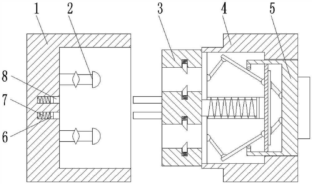
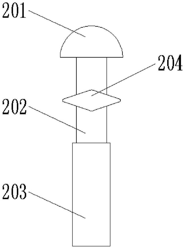
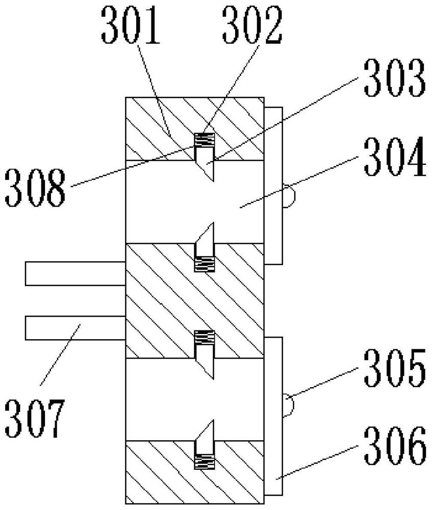
[0033] Attached below Figure 1-8 , clearly and completely describe the technical solutions in the embodiments of the present invention, obviously, the described embodiments are only some of the embodiments of the present invention, not all of the embodiments. Based on the embodiments of the present invention, all other embodiments obtained by persons of ordinary skill in the art without making creative efforts belong to the protection scope of the present invention.

[0034] In describing the present invention, it should be understood that the terms "longitudinal", "transverse", "upper", "lower", "front", "rear", "left", "right", "vertical", The orientations or positional relationships indicated by "horizontal", "top", "bottom", "inner", "outer", etc. are based on the orientations or positional relationships shown in the drawings, and are only for the convenience of describing the present invention, rather than indicating or It should not be construed as limiting the inventi...


PUM


Abstract

The invention discloses a plug-in device for power supply, which comprises a first connecting piece and a second connecting piece. A fixing piece is installed inside the first connecting piece, and an installation groove is opened on the inner wall of the first connecting piece. A first spring and a first joint are installed inside the slot, one end of the first spring is fixedly mounted on the inner wall of the installation slot, and the other end is fixed on the first joint, and the inside of the second connector is installed with a socket Components, connecting mechanisms and pushing mechanisms. In the present invention, the connection between the first joint and the second joint ensures normal power supply, the setting of the first spring can ensure that the first joint and the second joint are always in a connected state, and the cooperation between the plug-in piece and the fixing piece ensures the stability of the device. The electric appliance is always in the energized state, ensuring the safety of the electric appliance, and the setting of the second connecting piece and the pushing mechanism facilitates the separation of the first joint and the second joint, facilitates power-off, and greatly ensures the safety of electric use.

Description

technical field [0001] The invention belongs to the technical field of power supply, in particular to a plug-in device for power supply. Background technique [0002] With the application level of power technology and the improvement of living standards, the number of electrical equipment used in households is increasing, and there are more and more types of household appliances. More and more, when the traditional plug is matched with the power supply seat, it usually relies on friction to maintain the power supply state. When this kind of plug is accidentally bumped, it is easy to cause the plug to loosen or fall off, so it is easy to cause sudden power failure. It is easy to cause a certain impact on the electrical equipment, and in the traditional power supply seat, the power supply piece is connected with the outer end. Due to the curiosity of children, they will use external metal rods or metal pieces to insert into the In the power supply seat, these metal rods or me...

Claims


Application Information

Patent Timeline
Patent Type & Authority Patents(China)
IPC IPC(8): H01R13/502H01R13/629H01R13/703H01R24/00
CPCH01R24/00H01R13/629H01R13/502H01R13/7031
Inventor 段晓玉于凯陈超李冉冉任倩玉沈治文吕会来杨冬燕李超王怡高梓浩韩万鹏李毅李岩
Owner ZHANGQIU POWER SUPPLY CO OF STATE GRID SHANDONG ELECTRIC POWER CO
Learn More