A split coil structure and transformer

A technology of transformers and coils, applied in the field of transformers, can solve problems such as difficulty in controlling the output voltage matching degree, and achieve the effects of solving the problem of short-circuit impedance mismatch, reducing voltage changes, and low loss

Active Publication Date: 2021-07-13
TBEA INTELLIGENT ELECTRIC CO LTD +3
View PDF0 Cites 0 Cited by
  • Summary
  • Abstract
  • Description
  • Claims
  • Application Information

AI Technical Summary

Problems solved by technology

[0004] The technical problem to be solved by the present invention is to provide a split coil structure and a transformer containing the split coil structure to solve the problem of impedance and output voltage between each split winding in order to solve the above-mentioned shortcomings of the traditional axial three-split transformer technology. The matching degree is not easy to control, so as to improve the power supply quality of the transformer

Method used


Image

  • A split coil structure and transformer
  • A split coil structure and transformer
  • A split coil structure and transformer

Examples


Embodiment 1

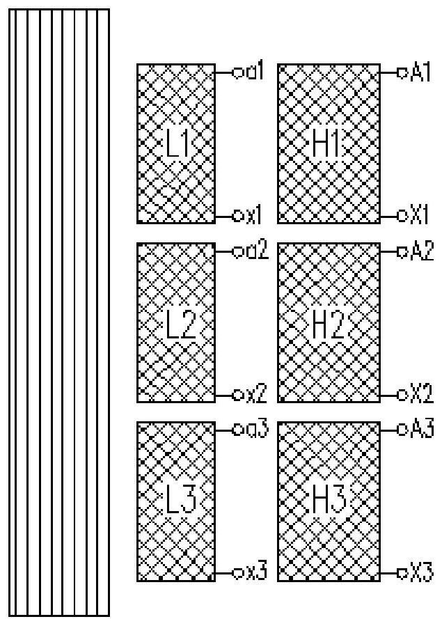
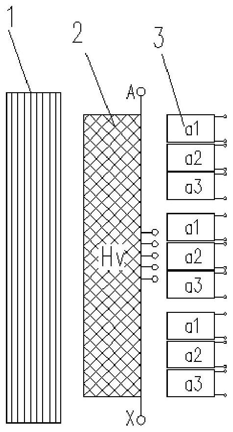
[0035] Such as Figure 2a As shown, this embodiment provides a split coil structure, including a core 1, a high-voltage winding 2 and a low-voltage winding 3, the high-voltage winding 2 and the low-voltage winding 3 are sequentially wound on the core 1, and the low-voltage winding 3 includes n The same winding units, n≥3, each winding unit is insulated from each other, each winding unit includes m split windings insulated from each other, m≥3, the corresponding same split windings in each winding unit are connected in parallel, and That is to say, the x-th split winding in each winding unit is connected in parallel with each x-th split winding in the remaining n-1 winding units, 1≤x≤m. That is, the first split winding in each winding unit is connected in parallel with each first split winding in the remaining n-1 winding units, and the second split winding in each winding unit is connected to the remaining Each of the second split windings in the n-1 winding units is connecte...

Embodiment 2

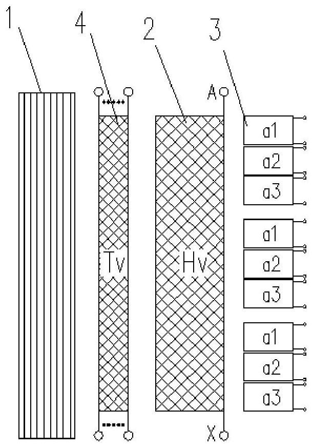
[0069] A transformer is disclosed in this embodiment, including Figure 3a / Figure 3b The split-coil configuration shown.

[0070] The split coil structure includes an iron core 1, a high voltage winding 2 and a low voltage winding 3, the high voltage winding 2 and the low voltage winding 3 are sequentially wound on the iron core 1, and the low voltage winding 3 includes n identical winding units arranged in the axial direction, n≥ 3. Each winding unit is insulated from each other, each winding unit includes m split windings insulated from each other, m≥3, and the same split winding corresponding to each winding unit is connected in parallel, that is to say, in each winding unit The xth split winding of is connected in parallel with the xth split winding of the remaining n-1 winding units, 1≤x≤m. That is, the first split winding in each winding unit is connected in parallel with each first split winding in the remaining n-1 winding units, and the second split winding in ea...


PUM


Abstract

The invention discloses a split coil structure, which includes an iron core, a high-voltage winding and a low-voltage winding. The high-voltage winding and the low-voltage winding are sequentially wound on the iron core. The low-voltage winding includes n identical winding units arranged in the axial direction, where n≧3, each The winding units include m split windings, where m≧3, and the same split windings corresponding to each winding unit are respectively connected in parallel. Correspondingly, a transformer including the above-mentioned split coil structure is also disclosed. The use of this split coil structure can solve the problem of severe ampere-turn imbalance between the high and low voltage windings of traditional axially split transformers, reduce the mutual interference of magnetic flux leakage between each split winding, and solve the short-circuit impedance mismatch problem between each split winding, The output voltage variation of each split winding is reduced, and the load loss of the transformer can be reduced at the same time, so as to realize high efficiency and energy saving.

Description

technical field [0001] The invention belongs to the technical field of transformers, and in particular relates to a split coil structure and a transformer including the split coil structure. Background technique [0002] Such as figure 1 As shown, the traditional split transformer structure is generally composed of the same number of split windings arranged in the axial direction of the core for both the high-voltage winding and the low-voltage winding. For example, the high-voltage winding is split into three along the axial direction, and the low-voltage winding is split into three along the axial direction. . [0003] In current industrial production, due to the split structure, most of the traditional split transformers can only achieve the axial three-split structure, and the traditional axial three-split transformers still have certain defects due to structural reasons, such as the magnetic flux leakage between the split windings Uneven interference leads to poor con...

Claims


Application Information

Patent Timeline
Patent Type & Authority Patents(China)
IPC IPC(8): H01F27/28H01F27/30H01F27/34H01F29/02
CPCH01F27/28H01F27/2823H01F27/306H01F27/346H01F29/02H01F2027/348
Inventor 鲁光辉刘波陈燕玲高娃
Owner TBEA INTELLIGENT ELECTRIC CO LTD
Why Eureka
Try Eureka