
Integrated limiting shafting with forward-backward 180-degree limiting

An integrated, position-limiting shaft technology, applied in the direction of pivot connection, can solve the problems of unrealizable and difficult position, and achieve the effect of simple operation

Pending Publication Date: 2020-12-25
JIUJIANG PRECISION MEASURING TECH RES INST
View PDF6 Cites 0 Cited by
  • Summary
  • Abstract
  • Description
  • Claims
  • Application Information

AI Technical Summary

Problems solved by technology

[0002] The limit shaft system is widely used in the field of turntables, and the limit mechanism is a very important component in the limit shaft system. The limit mechanism generally includes mechanical limit and electrical limit. The mechanical limit of the traditional limit mechanism It is separate from the electrical limit, and two independent spaces need to be reserved on the turntable equipment for installation, and it is difficult for the traditional ordinary mechanical limit mechanism to achieve the limit of ±180゜, and the limit angle is generally less than ±180゜
Although the existing limit mechanism can realize the integration of mechanical and electrical limit, it cannot realize the limit of ±180 ゜ or greater than ±180 ゜

Method used


Image

  • Integrated limiting shafting with forward-backward 180-degree limiting
  • Integrated limiting shafting with forward-backward 180-degree limiting
  • Integrated limiting shafting with forward-backward 180-degree limiting

Examples


Embodiment Construction

[0015] The present invention will be further described below in conjunction with the embodiments and accompanying drawings.

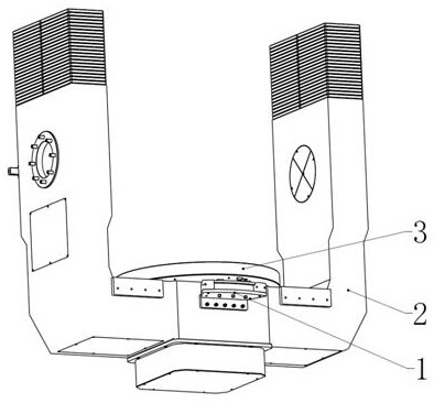
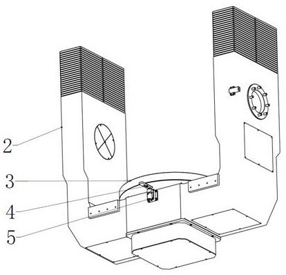
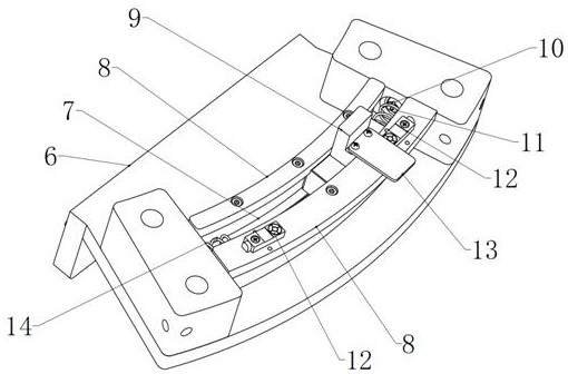
[0016] An integrated limit shaft system with a positive and negative 180° limit, including a "U"-shaped base 2, such as Figure 1-Figure 3 As shown, the limit mechanism 1 and the locking pin shaft 5 are respectively fixedly installed on both sides of the bottom of the "U"-shaped base 2, and the movable shaft system 3 is installed on the upper end surface of the bottom of the "U"-shaped base 2, and the movable shaft The side of system 3 is equipped with limited movable rod 4, and described limited mechanism 1 comprises chute support 6, and chute support 6 is provided with chute 7, is provided with slide block 9 in chute 7, and the two ends of chute 7 All are provided with limit stopper 14, and one end of limit stopper 14 is positioned at chute 7 is provided with spring support 11, and spring 10 is installed on spring support 11, and described slide block...


PUM


Abstract

The invention provides an integrated limiting shafting with forward-backward 180-degree limiting. The integrated limiting shafting comprises a U-shaped base, wherein a limiting mechanism and a lockingpin shaft are respectively and fixedly mounted on two side surfaces of the bottom of the U-shaped base; a movable shafting is mounted on the upper end surface of the bottom of the U-shaped base; a limiting movable rod is mounted on the side surface of the movable shafting; the limiting mechanism comprises a sliding groove bracket; a sliding groove is formed in the sliding groove bracket; a sliding block is arranged in the sliding groove; limiting stop blocks are arranged at two ends of the sliding groove; a spring support is arranged at one end, in the sliding groove, of each limiting stop block; springs are mounted on the spring supports; the sliding block is limited in the sliding groove through a sliding groove cover fixed at the two sides of the sliding groove; a contact switch plateis fixed at the upper end of the sliding block; and contact switches matched with the contact switch plate are fixed on the sliding groove cover. According to the integrated limiting shafting, the limiting movable rod can achieve the zero-position locking function of the limiting shafting, and can be used as a thrust part for pushing the sliding block in the rotating process of the movable shafting, so that operation is simple and use is convenient.

Description

technical field [0001] The invention relates to a one-piece limit shaft system with positive and negative 180° limit. Background technique [0002] The limit shaft system is widely used in the field of turntables, and the limit mechanism is a very important component in the limit shaft system. The limit mechanism generally includes mechanical limit and electrical limit. The mechanical limit of the traditional limit mechanism It is separate from the electrical limit, and two independent spaces need to be reserved on the turntable equipment for installation, and it is difficult for traditional ordinary mechanical limit mechanisms to achieve a limit of ±180 ゜, and the limit angle is generally less than ±180 ゜. However, although the existing limit mechanism can realize the integration of mechanical and electrical limit, it cannot realize the limit of ± 180 ゜ or greater than ± 180 ゜. Contents of the invention [0003] The purpose of the present invention is to provide a positi...

Claims


Application Information

Patent Timeline
Patent Type & Authority Applications(China)
IPC IPC(8): F16C11/12F16C11/10
CPCF16C11/12F16C11/10
Inventor 喻杰勇余沛简丹肖小刚
Owner JIUJIANG PRECISION MEASURING TECH RES INST
Learn More