Regulating valve

A technology for regulating valves and valve chambers, which is applied in the field of regulating valves, and can solve problems such as broken pipes of regulating valves, poor sealing performance of regulating valves, and small sealing specific pressure, and achieve the effects of enhancing sealing performance, increasing sealing specific pressure, and enhancing sealing performance

Inactive Publication Date: 2020-12-29
邵玉刚
View PDF0 Cites 2 Cited by
  • Summary
  • Abstract
  • Description
  • Claims
  • Application Information

AI Technical Summary

Problems solved by technology

[0002] In the automatic control of modern factories, the regulating valve plays a very important role. The production of these factories depends on the correct distribution and control of the flowing medium. When the user uses the regulating valve, the high-pressure medium is compressed into a low pressure through the regulating valve. The medium is then used in the process pipeline. When the process pipeline is suspended, the medium pressure at the outlet of the regulating valve will continue to rise, and when the medium pressure rises to a certain value, the disc sealing surface of the regulating valve and the valve seat will The sealing surfaces are in contact with each other. Due to the small sealing specific pressure, the sealing of the regulating valve is poor, and the medium on the inlet side of the regulating valve will leak to the outlet side of the regulating valve. The pressure of the medium on the outlet side of the regulating valve will continue to rise, and it is easy to form a regulating valve. Accidents such as pipe rupture or explosion on the outlet side

Method used


Image

  • Regulating valve
  • Regulating valve
  • Regulating valve

Examples


Embodiment Construction

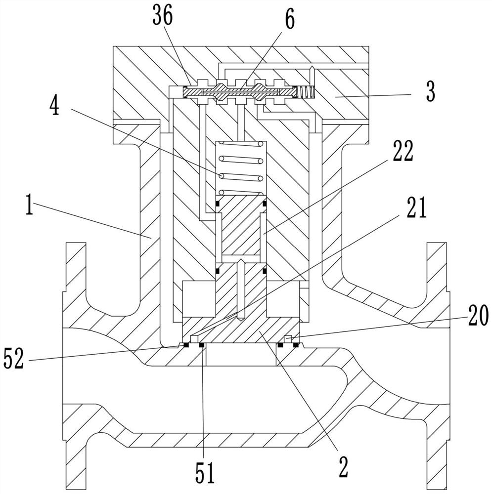
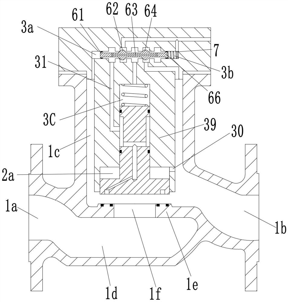
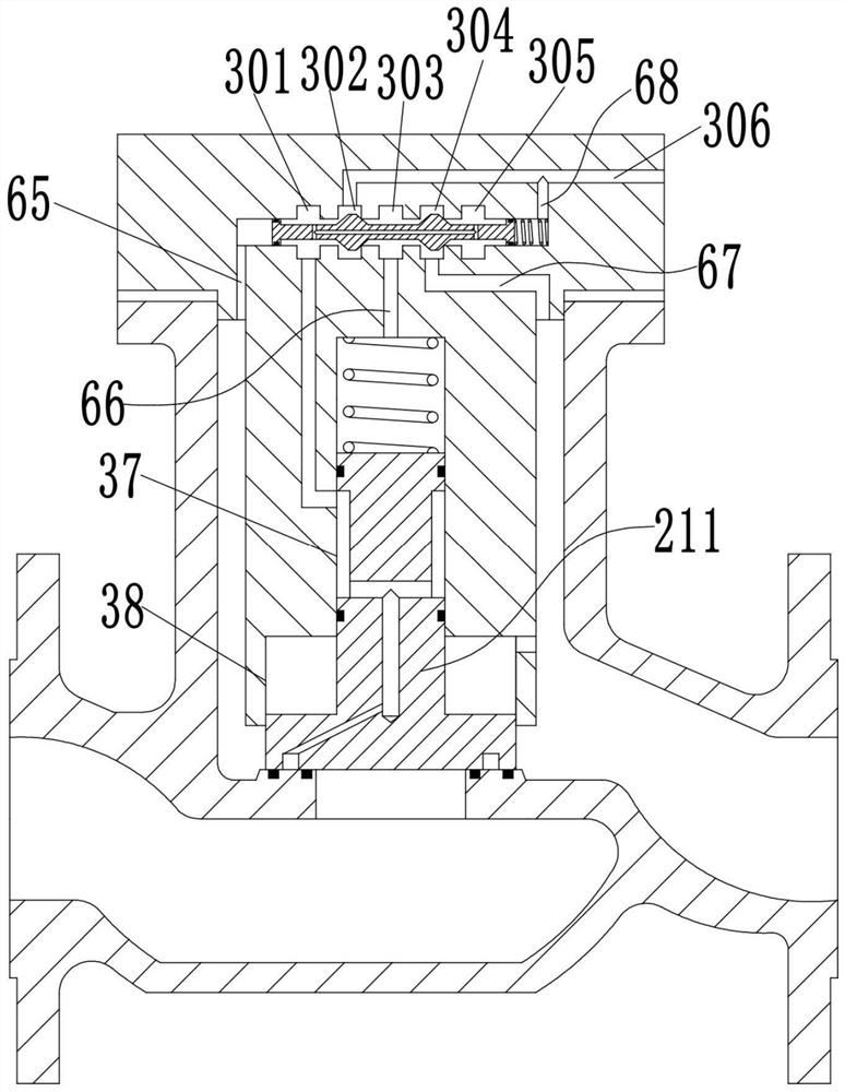
[0016] see Figure 1-3 As shown, the present invention provides a regulating valve, including a valve body 1, a valve cavity is provided in the valve body 1, a valve seat plate 1e is provided in the valve body 1, and the valve seat plate 1e separates the valve cavity It is formed into an upper valve chamber 1c and a lower valve chamber 1d, and the side of the valve body 1 is provided with an inlet pipe 1a communicating with the lower valve chamber 1d, and an outlet pipe 1b communicating with the upper valve chamber 1c; inside the valve seat plate 1e There is a valve hole 1f for communicating with the upper valve chamber 1c and the lower valve chamber 1d; the valve body 1 is fixedly installed with a valve cover 3 at the upper opening of the upper valve chamber 1c, and the outer surface of the valve cover 3 is provided with a dismounting Charge hole 306, the inner side of the valve cover 3 is provided with a boss 39 along the axial direction of the valve hole 1f, the lower end o...


PUM


Abstract

The invention discloses a regulating valve. The regulating valve comprises a valve body, a valve cavity is formed in the valve body, a valve seat plate is arranged in the valve body, the valve seat plate divides the valve cavity into an upper valve cavity body and a lower valve cavity body, and an inlet pipe and an outlet pipe are arranged on the side face of the valve body; a valve hole is formedin the valve seat plate; a valve deck is fixedly installed at the upper end of the valve body, an unloading hole is formed in the outer side face of the valve deck, a protruding column is arranged onthe inner side of the valve deck, a first sliding hole is upwards formed in the lower end of the protruding column, a second sliding hole is upwards formed in the blind end of the first sliding holein the protruding column, a valve clack is slidably connected in the first sliding hole, a sliding block is arranged on the valve clack, a first cavity is formed in the first sliding hole, a second cavity is formed in the second sliding hole, and a pressure regulating spring is arranged in the second cavity; an annular unloading groove is formed in the lower end of the valve clack; and a valve control assembly is arranged in the valve deck. The regulating valve not only is reliable in sealing, but also can prevent the outlet side pipeline from being broken or exploded due to overlarge pressure.

Description

technical field [0001] The invention belongs to the technical field of regulating valves, in particular to a double-seat regulating valve. Background technique [0002] In the automatic control of modern factories, the regulating valve plays a very important role. The production of these factories depends on the correct distribution and control of the flowing medium. When the user uses the regulating valve, the high-pressure medium is compressed into a low pressure through the regulating valve. The medium is then used in the process pipeline. When the process pipeline is suspended, the medium pressure at the outlet of the regulating valve will continue to rise, and when the medium pressure rises to a certain value, the disc sealing surface of the regulating valve and the valve seat will The sealing surfaces are in contact with each other. Due to the small sealing specific pressure, the sealing of the regulating valve is poor, and the medium on the inlet side of the regulatin...

Claims


Application Information

Patent Timeline
Patent Type & Authority Applications(China)
IPC IPC(8): F16K1/36F16K1/46F16K17/28
CPCF16K1/36F16K1/465F16K17/28
Inventor 吴虹许长鑫亓丽红
Owner 邵玉刚
Why Eureka
Try Eureka