Cable crossing device for power construction

A technology of electric power construction and cable wires, which is applied in the direction of overhead lines/cable equipment, etc., can solve problems such as low safety, affecting the safety of road vehicles, and shaking of scaffolding, so as to improve work efficiency, ensure service life, and ensure stability.

Active Publication Date: 2021-01-05
STATE GRID SHANDONG ELECTRIC POWER CO QIHE POWER SUPPLY CO
View PDF11 Cites 3 Cited by
  • Summary
  • Abstract
  • Description
  • Claims
  • Application Information

AI Technical Summary

Problems solved by technology

[0003] The existing transmission line crossing support frame generally uses scaffolding to erect the support frame on both sides of the road, and the cables are erected on the upper part of the support frame, which has the following defects: 1) The scaffolding needs to be erected manually, and the efficiency of its erection is low, resulting in The construction period of the cable erection is longer; 2) the stability of the scaffold itself is poor, especially when the height of the scaffold is high, the upper part of the scaffold will shake or even collapse, threatening the personal safety of construction workers and road passers-by; and When the cable is erected, the cable needs to be pulled, and the cable generates friction on the upper end of the scaffold, which intensifies the shaking of the scaffold and lowers the safety; 3) The cable between the two ends of the scaffold is bent under its own gravity, making the cable The support height of the cable is reduced, which affects the safety of road vehicles

Method used


Image

  • Cable crossing device for power construction
  • Cable crossing device for power construction
  • Cable crossing device for power construction

Examples


Embodiment Construction

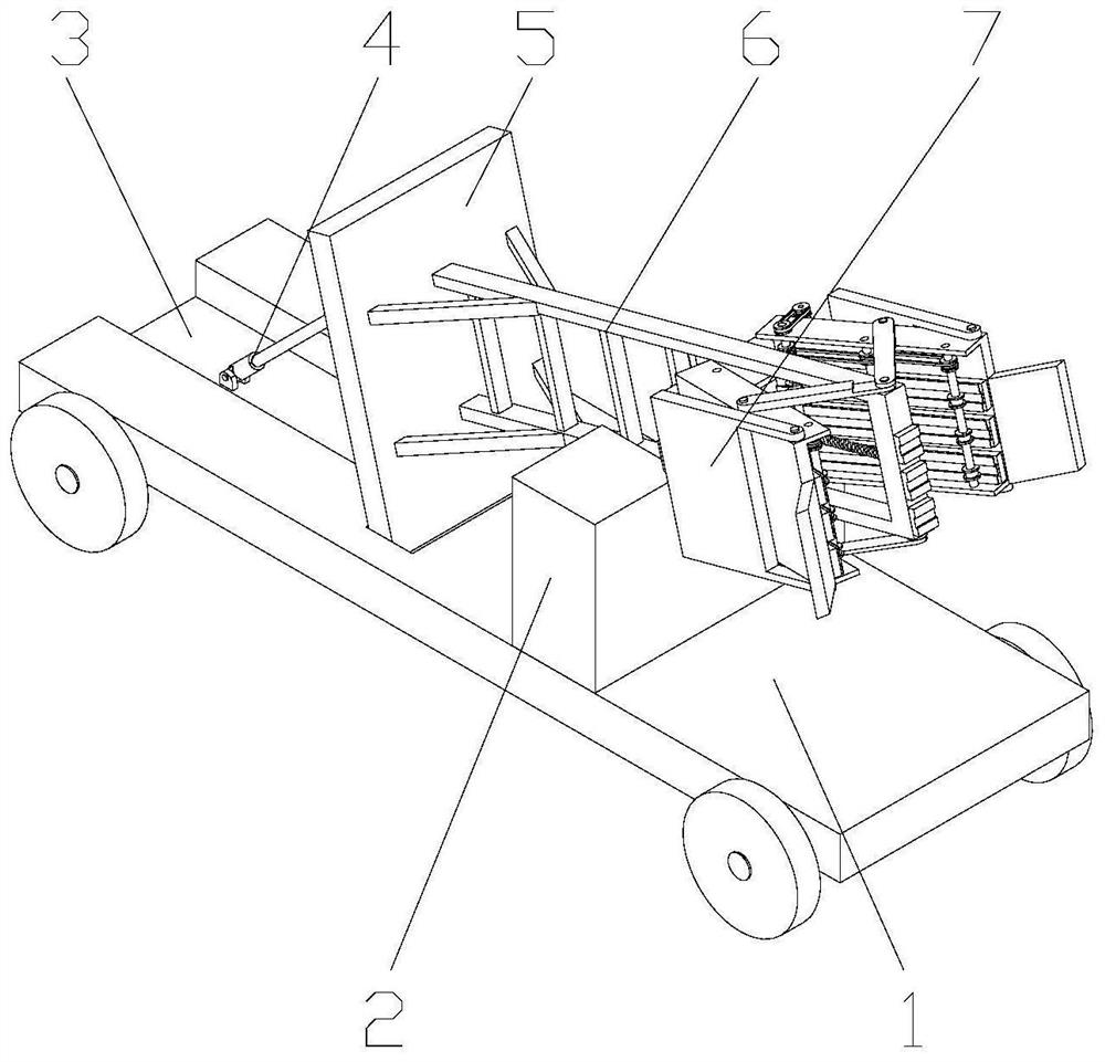
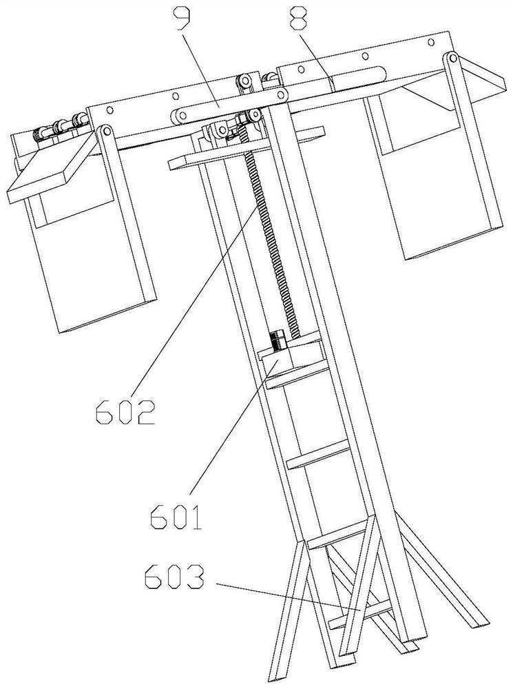
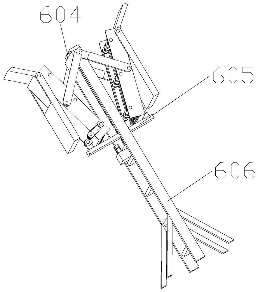
[0037] Attached below Figure 1-10 , clearly and completely describe the technical solutions in the embodiments of the present invention, obviously, the described embodiments are only some of the embodiments of the present invention, not all of them. Based on the embodiments of the present invention, all other embodiments obtained by persons of ordinary skill in the art without making creative efforts belong to the protection scope of the present invention.

[0038] In describing the present invention, it should be understood that the terms "longitudinal", "transverse", "upper", "lower", "front", "rear", "left", "right", "vertical", The orientations or positional relationships indicated by "horizontal", "top", "bottom", "inner", "outer", etc. are based on the orientations or positional relationships shown in the drawings, and are only for the convenience of describing the present invention, rather than indicating or It should not be construed as limiting the invention by impl...


PUM


Abstract

The invention discloses a cable crossing device for power construction. The device comprises a transport vehicle, a support frame and a mounting table are mounted on the transport vehicle, wherein a lifting mechanism is mounted on the mounting table, a support mechanism is mounted at the top of the lifting mechanism, and a first connecting rod and a second connecting rod are mounted on the liftingmechanism; one ends of the first connecting rod and the second connecting rod are installed on the lifting mechanism, and the other ends are installed on the supporting mechanism. The device only needs to be moved to a working position under the action of a transport vehicle, assembling and disassembling are not needed, the working efficiency is greatly improved, the lifting mechanism can expandthe supporting mechanism, the purpose of crossing obstacles is achieved, erecting of cables is achieved, the lifting mechanism can fold the supporting mechanism, and the device is convenient to use and high in practicability; safety of the device in the transportation process is guaranteed, the stability of the device is guaranteed through the arrangement of the two supporting mechanisms, the situation that the device inclines and even is damaged due to uneven stress in the working process is prevented, and the service life of the device is greatly guaranteed.

Description

technical field [0001] The invention belongs to the technical field of electric power construction, in particular to a cable crossing device for electric power construction. Background technique [0002] The transmission line crossing support frame is a common equipment in the field of electric power construction. When erecting a new power grid or temporary construction of the power grid, there are often situations where transmission lines cross roads or existing communication lines. Erection of transmission lines across the support frame. [0003] The existing transmission line crossing support frame generally uses scaffolding to erect the support frame on both sides of the road, and the cables are erected on the upper part of the support frame, which has the following defects: 1) The scaffolding needs to be erected manually, and the efficiency of its erection is low, resulting in The construction period of the cable erection is longer; 2) the stability of the scaffold it...

Claims


Application Information

Patent Timeline
Patent Type & Authority Applications(China)
IPC IPC(8): H02G1/04
CPCH02G1/04
Inventor 段元亭周龙灿李红艳张林刘菲董英芳杨博周爱华
Owner STATE GRID SHANDONG ELECTRIC POWER CO QIHE POWER SUPPLY CO
Why Eureka
Try Eureka