Shielded cable deconcentrator

A technology of shielded cables and splitters, which is applied in the direction of cable joints, cable accessories, cable installation, etc., and can solve the problems of damaging the insulation isolation of cables and the structural integrity of electromagnetic isolation

Pending Publication Date: 2021-01-08
CHINA AVIATION OPTICAL-ELECTRICAL TECH CO LTD
View PDF0 Cites 0 Cited by
  • Summary
  • Abstract
  • Description
  • Claims
  • Application Information

AI Technical Summary

Problems solved by technology

It is recognized in the industry that electrical conductors can be connected by cold pressing, soldering or sonic welding. However, since a section of the shielding layer and the inner insulating layer are stripped, the integrity of the insulation isolation and electromagnetic isolation structure of the cable is destroyed. This not only needs to solve the problem of

Method used


Image

  • Shielded cable deconcentrator
  • Shielded cable deconcentrator
  • Shielded cable deconcentrator

Examples


Embodiment 1

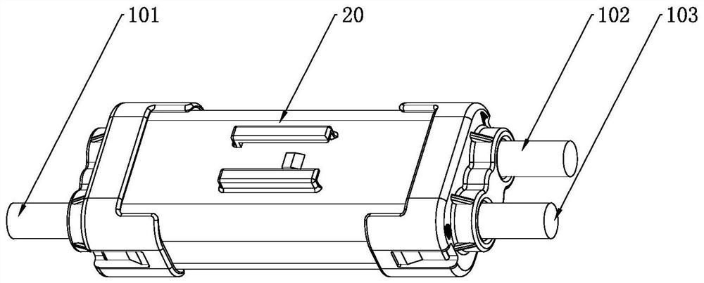
[0036] see Figure 1 to Figure 9 , is an embodiment of a cable assembly using a splitter of the present invention. This embodiment is used to realize the connection from one shielded cable to two shielded cables. The cross section of the splitter used in this embodiment is approximately rounded rectangle.

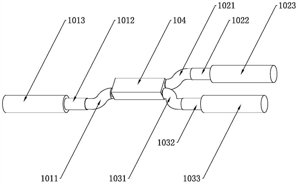
[0037] figure 2 A non-limiting example of three first shielded cables 101 , second shielded cables 102 and third shielded cables 103 spliced ​​together is shown. The electrical conductors of the three shielded cables are joined together by existing techniques such as cold crimping, soldering or sonic welding to form the connector 104 . To enable the connection of the electrical conductors, the outer sheaths 1013, 1023, 1033, the shielding layers 1012, 1022, 1032 and parts of the inner insulating layers 1011, 1021, 1031 are removed from the electrical conductors. At the same time, in order to maintain electrical insulation from the electrical conductor, the shielding lay...

Embodiment 2

[0045] see Figure 10 to Figure 18 , is another embodiment of a cable assembly using a splitter of the present invention. This embodiment is used to realize the connection from one shielded cable to two shielded cables. The appearance of the splitter used in this embodiment is similar to a funnel shape.

[0046] Figure 11 A non-limiting example of three first shielded cables 101 , second shielded cables 102 and third shielded cables 103 spliced ​​together is shown. The difference between this embodiment and Embodiment 1 is that: in this embodiment, the axis of the first shielded cable 101 is located between the axis of the second shielded cable 102 and the axis of the third shielded cable 103 .

[0047] The three shielded cables 101, 102, and 103 connected together are installed on the splitter 20 to form a cable assembly, and the splitter provides the cable assembly with a channel for accommodating the connection position of the shielded cables and overall reinforcement an...


PUM


Abstract

The invention discloses a shielded cable deconcentrator which comprises: a shielding piece used for being attached to shielding layers of a plurality of shielded cables connected together; a conductive shell which is used for providing an axial channel for surrounding the connection positions of the plurality of shielding cables and the shielding piece, and is in contact with the shielding piece to realize the connection of the shielding layer; and sealing pieces which are arranged on the two sides of the axial channel and are connected with the conductive shell so as to carry out waterproof sealing on the connection positions of the plurality of shielding cables. According to the invention, through the axial channel of the conductive shell, electric insulation isolation of a connection position is realized; through the shielding piece which is in contact with the shielding layer of the shielding cable and the conductive shell at the same time, connection of multiple cable shielding layers is achieved, and electromagnetic interference is avoided; and waterproof sealing of the connection position is achieved through the sealing piece matched with the conductive shell.

Description

technical field [0001] The invention specifically relates to a splitter structure for realizing the connection of multiple shielded cables. Background technique [0002] The inner wiring harness of new energy vehicles includes low-voltage signal wiring harness and high-voltage power wiring harness. The voltage and current changes of the power wiring harness will interfere with the signal wiring harness, so it is necessary to use shielded cables for prevention. The recognized shielded cable is a cable with a coaxial structure, which includes an electrical conductor, an inner insulating layer, a shielding layer, and an outer sheath from the inside to the outside. Composition of woven mesh. When there is a connection requirement for shielded cables, it is necessary to strip off a section of the outer sheath, shielding layer and inner insulation layer to expose the electrical conductor. It is recognized in the industry that electrical conductors can be connected by cold pressi...

Claims


Application Information

Patent Timeline
IPC IPC(8): H02G15/08H02G15/113H02G15/117
CPCH02G15/085H02G15/113H02G15/117
Inventor 郑文杰郑颖慧白光辉于香香余本钢牛冬冬
Owner CHINA AVIATION OPTICAL-ELECTRICAL TECH CO LTD
Why Eureka
Try Eureka