Switching monitoring device

A technology of switch monitoring and switch operation, applied in the direction of measuring device, measuring electricity, measuring electrical variables, etc., can solve problems such as increasing the production cost of relays, and achieve the effect of large diagnostic coverage

Pending Publication Date: 2021-01-12
PHOENIX CONTACT GMBH & CO KG
View PDF20 Cites 2 Cited by
  • Summary
  • Abstract
  • Description
  • Claims
  • Application Information

AI Technical Summary

Problems solved by technology

Positive contact control and / or feedback by means of auxiliary contacts has the disadvantage of increasing production costs in relay manufacture

Method used


Image

  • Switching monitoring device
  • Switching monitoring device
  • Switching monitoring device

Examples


Embodiment Construction

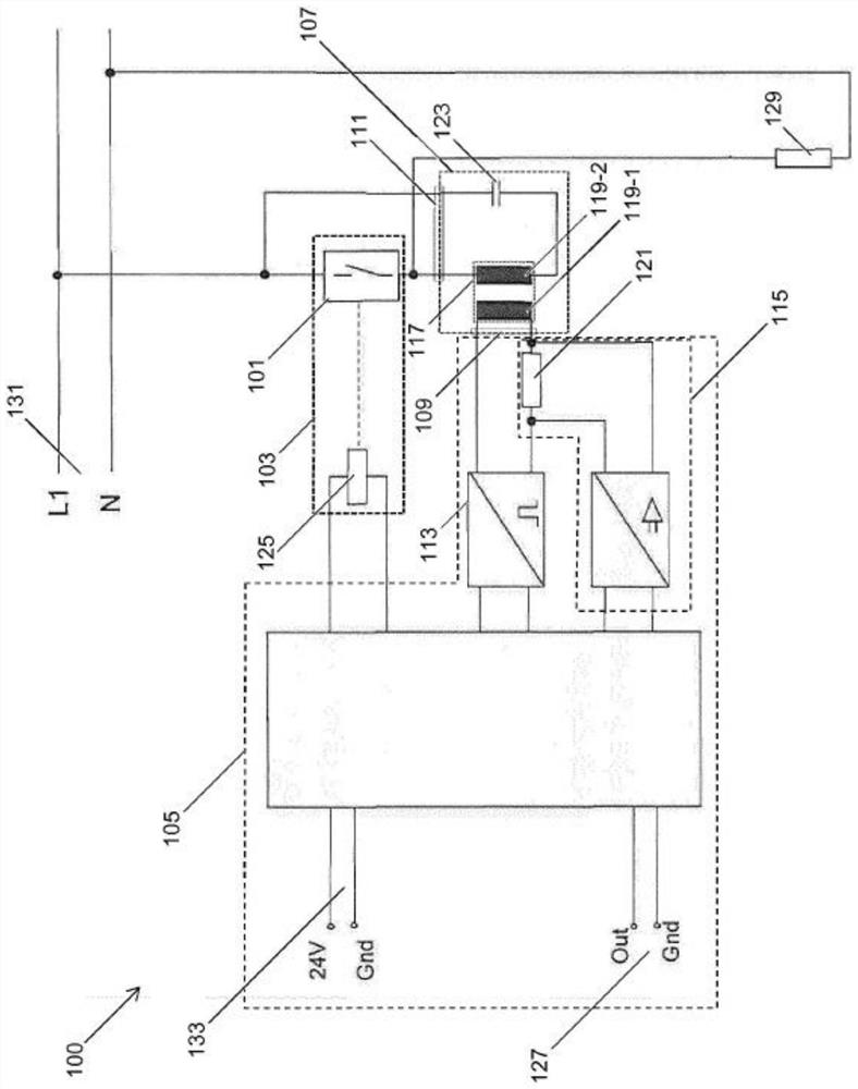
[0140] figure 1 It is a schematic diagram of the switch monitoring device 100 for monitoring the switching operation of the relay switch contact 101 of the relay 103 . The switching monitoring device 100 has a controller 105 for generating control signals and activation signals for the switching contacts 101 of the switching relay.

[0141] The switching monitoring device 100 also includes an impedance circuit 107 with a signal input 109 and a signal output 111 . The controller 105 is used for applying the excitation signal to the signal input terminal 109 . The impedance circuit 107 is used to convert the excitation signal into a switch monitoring signal, and output the switch monitoring signal at the signal output terminal 111 for application to the relay switch contact 101 .

[0142] In addition, the controller 105 is configured to detect signal changes in the impedance circuit 107 , especially changes in the excitation signal and / or the switch monitoring signal, and to d...


PUM


Abstract

The disclosure comprises a switching monitoring device (100) for monitoring a switching operation of a relay switching contact (101) of a relay (103), the switching monitoring device (100) having thefollowing features: - a control terminal (102), which is designed to apply a control signal for switching the relay switching contact (101) to the relay switching contact (101); - a controller (105),which is designed to produce an excitation signal; and - an impedance circuit (107), having a signal input (109) and a signal output (111), wherein: - the controller (105) is designed to apply the excitation signal to the signal input (109); - the impedance circuit (107) is designed to convert the excitation signal into a switching monitoring signal and to output the switching monitoring signal atthe signal output (111) for application to the relay switching contact (101); - the controller (105) is also designed to monitor a change in a signal present at the impedance circuit (107) and, if the change in the signal is present, to detect a switching operation of the relay switching contact (101).

Description

technical field [0001] The invention relates to a switch monitoring device for monitoring the switching operation of a relay switch contact. Background technique [0002] In electrical automation, each actuator can be switched on and off by a relay. Among other things, it may be necessary to detect the actual switching operation of the relay switch contacts. In this type of detection, feedback is often obtained by switching the relay on and off with other auxiliary contacts. Alternatively, erroneous switching operations of the relay can also be prevented by implementing positive contact control. If a relay switching contact fails, for example due to a defective welded pushbutton, the switching operation of the other relay switching contacts and / or the connection of the welded pushbutton to other pushbuttons can be prevented by means of positive contact control. Positive contact control and / or feedback by means of auxiliary contacts has the disadvantage of increasing produ...

Claims


Application Information

Patent Timeline
Patent Type & Authority Applications(China)
IPC IPC(8): G01R31/327
CPCG01R31/3278
Inventor 彼得·肖尔茨埃尔玛·沙佩尔
Owner PHOENIX CONTACT GMBH & CO KG
Why Eureka
Try Eureka